CQ-RG131W
18
E
N
G
L
I
S
H
15
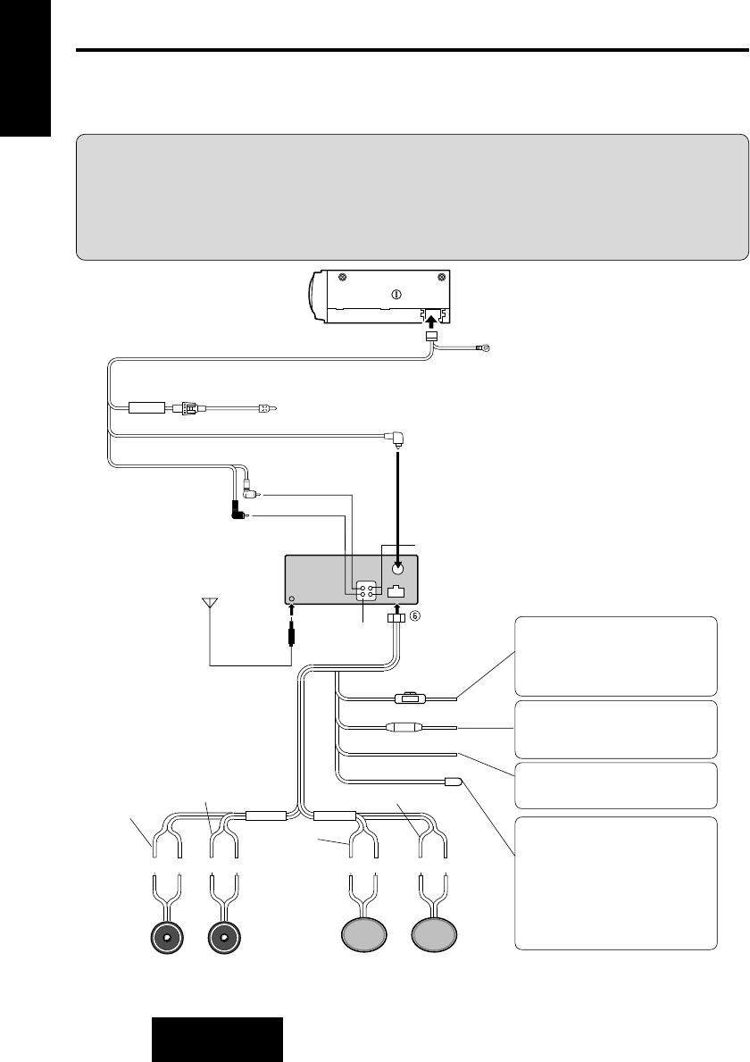
Electrical Connection
Cautions:
●
To prevent damage to the unit, be sure to follow the connection diagram below.
●
Remove the covering of the leads about 5 mm long from their end before connecting.
●
Do not insert the power connector into the unit until the wiring is completed.
●
Be sure to insulate any exposed wires from a possible short-circuit from the car chassis. Bundle
all cables and keep cable terminals free from touching any metal parts.
CQ-RG131W
Left
Speaker
(Front )
Right
Speaker
(Front )
Left
Speaker
(Rear)
Right
Speaker
(Rear)
(+)(–)(+)(–)(+)(–)(+)(–)
Antenna
Power Connector
(Red)
Resistor (1 kΩ)
(Yellow)
(Black)
(Violet w/Black Stripe)
(Blue)
(Gray w/Black Stripe)
Speaker Lead
CD • Changer
Input. connector
(White w/Black
Stripe)
(White)
(Gray)
(Green w/Black
Stripe)
(Green)
(Violet)
Fuse(12 A)
L(White)
R(Red)
Preamp Out Connector
CX-DP88N
BATTERY LEAD (To Battery of Car)
Connect to the “BAT” terminal on the
fuse block of the car.
The power should be supplied continu-
ously to the yellow leads regardless of
the on/off position of the ignition key.
POWER LEAD
Connect to the “radio” power line of the
car or to the “IGN” or “ACC” terminal of
the fuse block.
GROUND LEAD
Connect to a well grounded metallic
part of your car.
MOTOR ANTENNA RELAY
CONTROL LEAD
(To Motor Antenna) (Max. 500 mA)
This lead is not intended for use with
switch actuated power antenna.
AMP·RELAY CONTROL POWER
LEAD
This lead is for connection to
Panasonic power amplifier.
()
CD Changer
Control Connector
Fuse (3A)
Extension Cord
(DIN/BATT/RCA/GND)
Ground Lead
(To a clean, bare metallic
part of your car)
Battery Lead
RCA Cord
DIN Cord
(White)
(Red)
(R)
(L)
BATTERY
(Option)
(Option)
(Yellow)
●
This unit can be connected to an optional CD changer (CX-DP88N). For details consult your
nearest Panasonic Service center.
●
For connection to a CD changer, refer to the operating instructions of the CD Changer (CX-
DP88N).


