


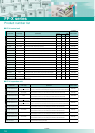
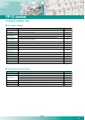
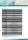
Item Specifications
Program method
Control method
Program memory
Program capacity
Operation processing speed
Basic instructions
Applied instructions
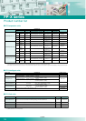
External inputs (X)
External outputs (Y)
Internal relay (R)
Special internal relay (R)
Link relay (L)
Timer/counter (T/C)
Data register (DT)
Link data register (LD)
Special data register (DT)
Index register (I0 to ID)
Master control relay (MCR)
Number of labels (LOOP)
Number of differentiations
Number of stepladders
Number of subroutines
Number of interruption programs
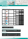
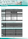
High-speed counter
*2
Pulse output
*3
Pulse catch input / interrupt input
Periodical interrupt
Potentiometer
Constant scan
Real-time clock
Flash ROM
backup
*6
Battery backup
Battery life
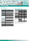
Password
Self-diagnosis function
Comment storage
PLC link function
Rewriting in RUN mode
Relay symbol method
Cyclic operation method
Flash ROM built-in (no battery backup required)
16k steps (C14), 32k steps (C30, C60)
Basic instruction 0.32Ms/step
111
216
1760 points
*1
1760 points
*1
4096 points
192 points
2048 points
12285 words (C14), 32765 words (C30, C60)
256 words
374 words
14 words
256 points
256 labels
Up to program capacity
1000 stages
500 subroutines
Relay output type: 15 programs (14 external, 1 constant)
Transistor output type: 9 programs (8 external, 1 constant)
0.5ms to 30s
2 points (0 to 1000) (C14, C30) 4 points (0 to 1000) (C60)
Possible
Equipped (usable only when AFPX-MRTC is installed)
*4
Data register (32,765 words)
Counter 16 points (1008 to 1023), Internal relay 128 points
(R2470 to R255F), Data register 55 words
The memory allocated in the storage area by the
system register (only when a battery is installed)
*5
C14: 1230 days (actual operation 10 years at 25°C)
C30, C60: 990 days (actual operation 10 years at 25°C)
C14: 780 days (actual operation 10 years at 25°C)
C30, C60: 680 days (actual operation 10 years at 25°C)
(More than two batteries can be installed in C30 and C60.
In this case, the battery life is extended several times)
Capable (4 or 8 characters selectable)
Watch dog timer, program syntaxcheck
Capable (328KB) (backup battery not required)
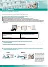
Max. 16 units, link relay 1024 points, link register 128 words
(No data transfer or remote programming)
Capable
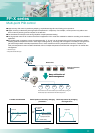
Backup by F12,
P13 commands
Auto-backup
at power failure
(when no power
is supplied)
After installing
AFPX-MRTC
Before installing
AFPX-MRTC
Built-in (Transistor output): single-phase 8ch (50kHz x 4ch + 10kHz x 4ch)
Built-in (Relay output): single-phase 8ch (10kHz x 8ch)
Pulse I/O cassette: single-phase 2ch (80kHz x 2ch)
Built-in (Transistor output): 100kHz x 2ch + 20kHz x 2ch
Pulse I/O cassette: One unit (one axis) 100kHz, or two units (two axes) 80kHz
Relay output type: Total 14 points (including the high-speed counter)
Transistor output type: Total 8 points (including the high-speed counter)
Total 1024 points: timer capable of counting
(1ms, 10ms, 100ms, 1s) x 32767
Counter capable of counting 1 to 32767
Notes:
*1 The actual usable number of points is restricted by the hardware.
*2 Specification at the rated input voltage of 24V DC, 25°C. Frequency may be lower due to the voltage and temperature.
*3 Max frequency may vary by the method of operation. Please refer to the manual for details.
*4 Calendar accuracy at 0°C: 119sec/month or less, 25°C: 51 sec/month or less, 55°C: 148 sec/month or less (Real-time clock requires a battery.)
*5 When data is stored in the storage area while the battery is not installed, the data is not cleared and the data value may be indefinite. The same condition occurs when the battery is exhausted.
*6 The number of possible rewrites is 10,000 or less.
21
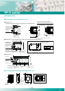
FP-X series
Control specifications
Specifications
01/2008