


ST
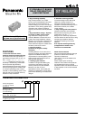
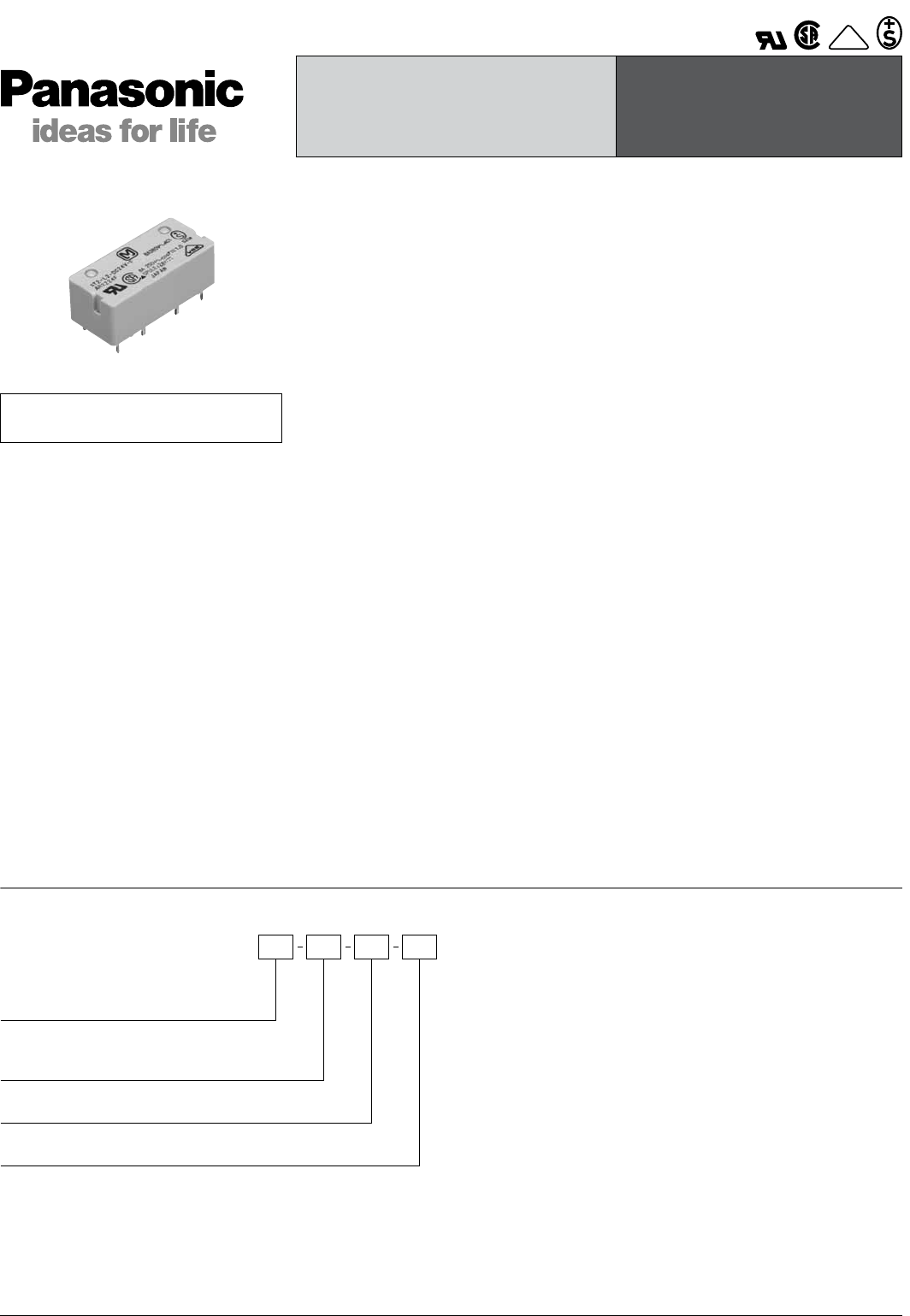
ORDERING INFORMATION
IC DRIVABLE PC BOARD
RELAY FOR INDUCTIVE
LOAD SWITCHING
ST RELAYS
VDE
FEATURES
1. Even with small form factor,
sensitive enough for direct IC-driving
The dimensions of this high-density 4-
gap balanced armature are 31 mm × 14
mm × 11 mm 1.220 inch × .551 inch ×
.433 inch. Despite this small size, high
sensitivity is achieved by a mechanism
that incorporates high-efficiency
polarized magnetic circuits along with our
exclusive spring alignment method. With
an minimum operating power of about
150 mW, nominal operating power of 240
mW, this relay can be directly driven by
transistor or chip controllers.
RoHS Directive compatibility information
http://www.mew.co.jp/ac/e/environment/
2. High switching capability
High contact pressure, low contact
bounce, and forced separation structure
that radically improves resistance to
contact welding (1 Form A 1 Form B type
equivalent to TV-3). Strong against lamp
inductive loads, maximum switching
capacity has reached 3,040 VA (8A 380V
AC).
3. High breakdown voltage – Optimal
for control in 250 V power circuits
High breakdown voltage has been
achieved. Between contacts and coil of
3,750 Vrms; Surge breakdown voltage
between coil and contact of 6,000 V, and
between open contacts of 1,200 Vrms
mean that these relays are suitable even
for 250 V power circuit control.
4. Improved stability
Conforms to all types of safety
standards.
Insulating distance of more than 3 mm
secured. Complies with Japan Electrical
Appliance and Material Safety Law
requirements for operating 200 V power
supply circuits, and conforms with UL,
CSA and VDE standards.
5. Latching types available
In addition to single side stable types,
convenient 2 coil latching types with
memory functions are also available.
Moreover, we offer 2 Form A
specifications which, with double pole
switching for applications such as 250 V
power circuit switching, can enable safer
designs.
6. Automatic cleaning possible
The sealed design means that these
relays can undergo immersion in
automatic washing systems and are
suitable for automatic soldering. Even in
difficult environments, the contacts
remain reliable.
7. Easy to design PC board patterns
Features 4/10 dual-in-line terminals.
Because the lead spacing has a pitch
greater than 7.54 mm .297 inch,
designers can make easy adjustments
with the width of the land size. This, along
with the large insulation distance,
simplifies the drawing of PC board
patterns.
8. To improve soldering efficiency,
preapplication of solder to the
terminals is recommended.
About Cd-free contacts
We have introduced Cadmium free type
products to reduce Environmental
Hazardous Substances.
(The suffix “F” should be added to the
part number)
Please replace parts containing
Cadmium with Cadmium-free products
and evaluate them with your actual
application before use because the life of
a relay depends on the contact material
and load.
Contact material
F: AgSnO2 type contact
Coil voltage
DC 3, 5, 6, 9, 12, 24, 48 V
Contact arrangement
1: 1 Form A 1 Form B
2: 2 Form A
ST F
Operating function
Nil:
L2:
Single side stable
2 coil latching
Note: UL/CSA, VDE, SEV type is standard.
All Rights Reserved © COPYRIGHT Matsushita Electric Works, Ltd.