


ST
PRECAUTIONS FOR USE (SOCKET)
ACCESSORIES
ST RELAYS
SOCKET
VDE
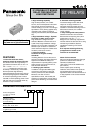
ST relay socket
ST-PS
PC board terminal socket
ST-SS
Solder terminal socket
FEATURES
1. Possible to fit or remove the chassis
with one touch (t = 0.6 mm to 2.2 mm
.024 inch to .087 inch)
2. Easy design of PC board pattern
(2.54 mm x 4 pitch DIL terminal array)
RoHS Directive compatibility information
http://www.mew.co.jp/ac/e/environment/
3. Complies with Japan Electrical
Appliance and Material Safety Law.
(UL and VDE certification)
4. High breakdown voltage.
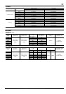
SPECIFICATIONS
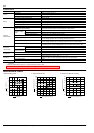
DIMENSIONS
(Unit: mm inch)
Item Specifications
Breakdown voltage (Initial)
Between contact and coil: 4,000 Vrms for 1 min. (Detection current: 10 mA)
Between contact and terminal: 2,000 Vrms for 1 min.
Insulation resistance (Initial) Min. 1,000 MΩ between terminals (500V DC)
Heat resistance 150°C 302°F for 1 hr
Max. continuous current 10 A
Relay insertion life 15 times
ST-PS ST-SS
31.6
1.244
35.4
1.394
16.6
.654
8
1
7
2
6
3
5
4
14.6
.575
16.4
.646
10.16
.400
1.05
.041
0.3
.012
5.5
.217
4
.158
4.3
.169
0.27
.011
10.16
.400
7.62
.300
7.62
.300
31.6
1.244
35.4
1.394
16.6
.654
8
1
7
2
6
3
5
4
14.6
.575
16.4
.646
10.16
.400
2.3
.090
0.3
.012
5.5
.217
4
.158
5.3
.209
0.27
.011
10.16
.400
7.62
.300
7.62
.300
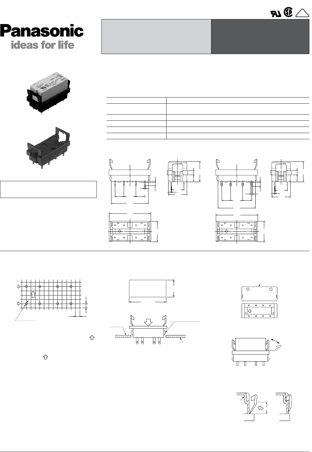
1. PC board mounting method
PC board pattern
The terminal configuration is symmetrical
on the left and right, so an arrow mark
is stamped on the socket to prevent mis-
insertion. We recommend printing the
same arrow mark on the component
mounting side (side opposite from
pattern) of the PC board. In this case, the
terminal configuration becomes the
terminal nos. noted near the drilling
holes.
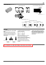
2. Chassis cutout
Chassis cutting dimensions
If the chassis hole is punched with a
press, set so the release R on the front
side (A side).
The range for chassis thickness is 0.6 to
2.2 mm .024 to .087 inch.
3. Relay mounting and removal
(1) Align the directions of the relay and
socket.
(2) Insert the relay all the way in, so it is
securely in place.
(3) Press the part indicated by A in the B
direction, and fasten by placing the hook
on the relay.
(4) When removing the relay, completely
release the hooks on both sides and pull
the relay out.
2.54
.100
8-1.5 DIA.
8-.060 DIA.
87 65
12 34
2.54
.100
Contact
terminal
interval
Coil
terminal
interval
15.0±0.2
.591±.008
32.5±0.1
1.280±.004
Claw for chassis
fastening
Chassis t = 0.6 to 2.2
.024 to .087
Press
A side
Relay
Hinge
mechanism
Relay case
cross-section
B
(Fastening complete)(Before fastening)
A
All Rights Reserved © COPYRIGHT Matsushita Electric Works, Ltd.