


ST
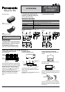
2. Specifications
Notes: *1 This value can change due to the switching frequency, environmental conditions, and desired reliability level, therefore it is recommended to check this with the
actual load.
*2 Wave is standard shock voltage of ±1.2×50µs according to JEC-212-1981
*3 Refer to 6. Conditions for operation, transport and storage mentioned in AMBIENT ENVIRONMENT
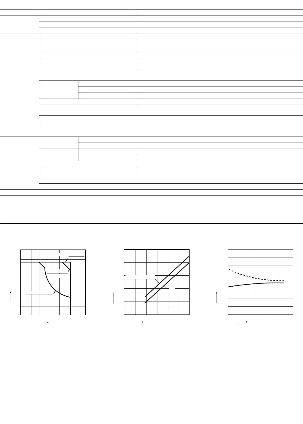
REFERENCE DATA
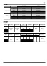
Characteristics Item Specifications
Contact
Arrangement 1 Form A 1 Form B, 2 Form A
Contact material Au-flashed AgSnO2 type
Initial contact resistance, max. Max. 30 mΩ (By voltage drop 6 V DC 1A)
Rating
Max. switching power (resistive load) 3,040 VA, 150 W
Max. switching voltage 380 V AC, 250 V DC
Max. switching current 8 A
Minimum operating power 150mW (Single side stable, 2 coil latching)
Nominal operating power 240mW (Single side stable, 2 coil latching)
Min. switching capacity (Reference value)*
1
100 mA 5V DC
Electrical
characteristics
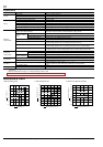
Insulation resistance (Initial)
(at 25°C, 50% relative humidity)
Min. 1,000MΩ (at 500V DC)
Measurement at same location as “Initial breakdown voltage” section.
Breakdown voltage
(Initial)
Between open contacts 1,200 Vrms for 1 min. (Detection current: 10 mA)
Between contact sets 2,000 Vrms for 1 min. (Detection current: 10 mA)
Between contact and coil 3,750 Vrms for 1 min. (Detection current: 10 mA)
Surge breakdown voltage (Initial)*
2
6,000 V (Between contact and coil)
Operate time [Set time] (at 20°C 68°F)
Max. 15 ms [Max. 15 ms]
(Nominal voltage applied to the coil, excluding contact bounce time.)
Release time [Reset time] (at 20°C 68°F)
Max. 10 ms [Max. 15 ms]
(Nominal voltage applied to the coil, excluding contact bounce time.) (without diode)
Temperature rise (at 60°C 140°F)
Max. 55°C
(By resistive method, nominal voltage applied to the coil; contact carrying current: 8A.)
Mechanical
characteristics
Shock resistance
Functional Min. 196 m/s
2
(Half-wave pulse of sine wave: 11 ms; detection time: 10µs.)
Destructive Min. 980 m/s
2
(Half-wave pulse of sine wave: 6 ms.)
Vibration resistance
Functional 10 to 55 Hz at double amplitude of 2 mm (Detection time: 10µs.)
Destructive 10 to 55 Hz at double amplitude of 3 mm
Expected life
Mechanical Min. 10
7
(at 180 cpm)
Electrical Min. 10
5
(8 A 250 V AC resistive) (ON : OFF = 1 s : 5 s)
Conditions
Conditions for operation, transport and storage*
3
Ambient temperature: –40°C to +60°C –40°F to +140°F;
Humidity: 5 to 85% R.H. (Not freezing and condensing at low temperature)
Max. operating speed 30 cps
Unit weight Approx. 10g .353 oz
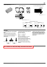
1. Max. switching power 2. Coil temperature rise 3. Influence of adjacent mounting
10 20 50 100 200 300
0.1
0.2
0.5
1
2
5
10
Voltage, V
Current, A
AC resistive load
DC resistive load
inductive load
AC
(cosϕ =0.4)
100
0.2 0.4 0.6 0.8 1.0 1.2
90
80
70
60
50
40
30
20
10
0
Temperature rise, °C
Coil operating power, W
0A
Contact current 8A
Pick-up voltage
Drop-out voltage
40
30
20
10
0
-10
-20
-30
-40
5101520
Rated of change, %
Inter-relay distance, mm
All Rights Reserved © COPYRIGHT Matsushita Electric Works, Ltd.