


ST
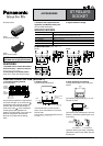
DIMENSIONS (Unit: mm inch)
NOTES
For Cautions for Use, see Relay Technical Information.
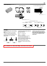
External dimensions
General tolerance: ±0.5 ±.020
31.0
1.220
11.0
.433
7.62
.300
7.62
.300
10.16
.400
10.16
.400
14
.551
0.3
.012
3.5 .138
1.0 1.0
.039 .039
0.6 dia. .024 dia.
0.3 .012
85
4321
7
6
1.0
.039
0.5
.020
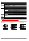
PC board pattern (Bottom view)
Tolerance: ±0.1 ±.004
2 coil latching
types only.
8-DIA. 1.4
.055
2.54
.100
2.54
.100
Schematic (Bottom view)
Single side stable 2 coil latching
1 Form A 1 Form B 2 Form A 1 Form A 1 Form B 2 Form A
14
5678
–+
14
5678
–+
12
5678
–+
34
+–
12
–+
34
+–
5678
(Deenergized condition) (Reset condition)
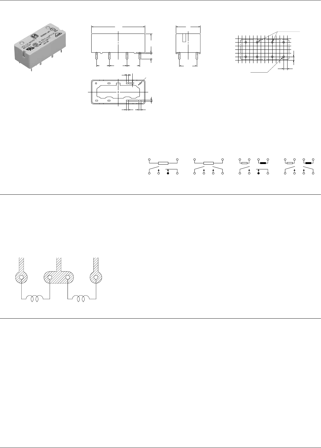
1. PC board patterns for 2 coil latching
types
When applying relays in power supply
operation circuits for finished products
regulated by the Electrical Appliance and
Material Safety Law, use the pattern
shown below.
2. Soldering should be done under the
following conditions:
1)
250°C 482°F within 10s
300°C 572°F within 5s
350°C 662°F within 3s
2) For automatic cleaning, the boiling
method is recommended. Avoid
ultrasonic cleaning which subjects the
relays to high frequency vibrations, which
may cause the contacts to stick.
It is recommended that a fluorinated
hydrocarbon or other alcoholic solvents
be used.
3. When using, please be aware that
the a contact and b contact sides of 1
Form A and 1 Form B types may go on
simultaneously at operate time and
release time.
1Te rminal No. 2 3 4
All Rights Reserved © COPYRIGHT Matsushita Electric Works, Ltd.