


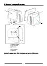
■ ID module Unit installation
Be sure to disconnect the power cable of the main block (POS Workstation) and confirm the
power is “OFF” before the operation below.
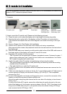
1. Conte
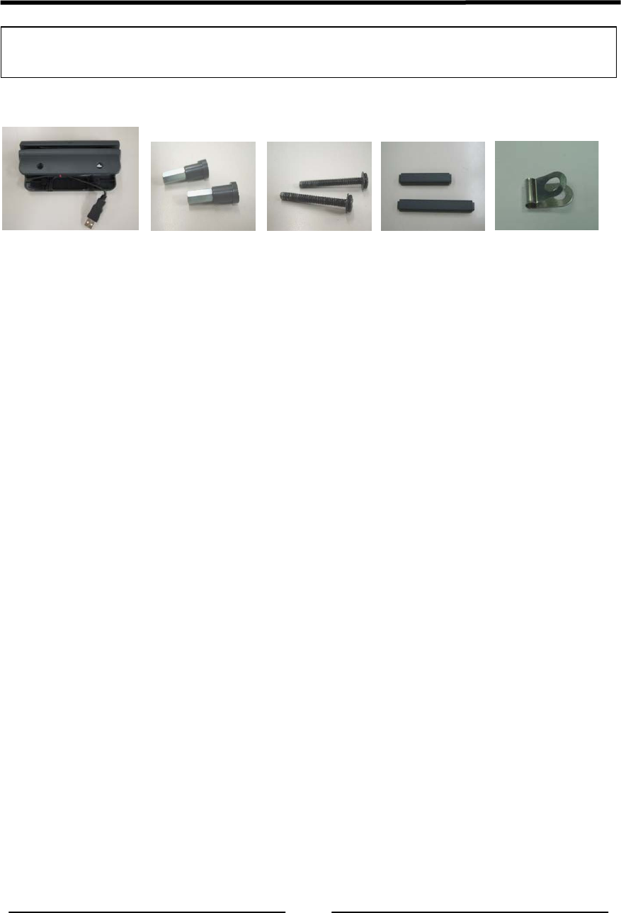
nts
Cabl
e cover
Peripheral screw (Use only
ID module 1pcs
Screw 2pcs
Long type 1pcs
2pcs Dallas KEY r
eader)
Short type 1
pcs
Cabl
e clamp 1pcs
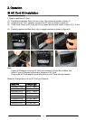
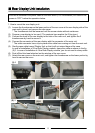
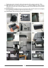
2. How
to mount the ID module unit (Please see the following pictures.)
(1) Place the main unit to make the display unit at right angle to the mounting table.
(2) Decide which side, right or left, of the display unit the ID module unit is mounted on.
(The contents here explain the case of the magnetic card reader mounting on the right
side.)
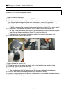
(3) Remove Display Unit. See Display Unit Installation.
(4) Remove the 2 screws on the rear side of the display unit using a screwdriver.
After removal of the screws, the peripheral screws can be removed from the front side of
the display unit.
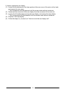
(5) Slide the USB cable cover toward you while pushing both sides of the USB cable cover at
the hinge section of the display unit inward to remove the cover.
(6) Prepare an ID module unit to be mounted.
* The ID module unit is supplied with 2 pieces of peripheral screws, 2 pieces of screws, 1
piece of long cable cover, and 1 piece of short cable cover as accessories. And Dallas
KEY reader is supplied with cable clamp
(7) Handle the cable of the ID module unit (positioning and securing the cable).
・ The guide channel is provided for cable positioning and securing inside the mounting
channel of the ID module unit.
・ The cable shall be run under the ID module unit.
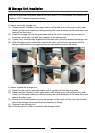
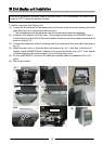
(8) Put the ID module unit in the position where the peripheral screws were removed on the
display unit.
(9) Cable cover has direction as shown in the fig. (9)-1. Insert salient portion of Cable cover to
concave portion of Display unit as shown in the fig. (9)-2 and (9)-3. Then completion
picture is fig. (9)
-4.
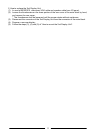
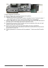
(10) In case of the magnetic card reader and fingerprint sensor, connect the connector of the
display unit with the connector of those module units.
Secure the cable along the guide channel on the rear side of the display unit as shown in
the fig. (10)-1.
In case of the Dallas KEY reader, secure the cable along the guide channel on the rear
side of the display unit. And loosen a screw as shown in the fig. (10)-2. Use clamp to clip
the ground of USB cable and put it in the position where the screw of fixing LCD hinge
were removed on the LCD hinge. (10)-3.
12