


Chapter 3 Register Setup of Each Function
62
3.9 8-bit Timer, Initializing Peripherals
There are five 8-bit timers comprising timer 0 to 4.
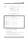
The timer comprises a binary counter, a compare register and a mode register. You can combine two 8-bit timers,
timer 0 and 1 or 2 and 3, to use as a 16-bit timer.
Binary counter
This counter counts a clock selected by the prescaler or the mode register.
Compare register
This register determines the time base of a timer by specifying clock number counted by the binary counter.
Mode register
This register enables/disables the timer operation, and selects the clock source. The setting content of the
mode register depends on the timer.
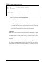
Timer 0:
BIT7: Unused
BIT6: Unused
BIT5: "0" Normal operation
"1" P22(IRQ2), pulse width measurement
BIT4: "0" Normal operation
"1" PWM operation
BIT3: "0" Stop count
"1" Count operation
BIT2, 1, 0: Clock source selection
000: High speed crystal clock oscillation frequency
001: Timer 0, prescaler output signal
010: Low speed crystal clock oscillation frequency
011: Synchronous low speed crystal clock oscillation frequency
110: Timer 0, pin input external signal
111: Synchronous timer 0, pin input external signal
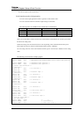
Timer 1:
BIT7: Not used
BIT6: Not used
BIT5: Not used
BIT4: "0" Normal operation
"1" Cascade connection