


Chapter 3 Register Setup of Each Function
67
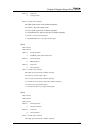
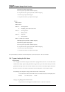
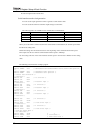
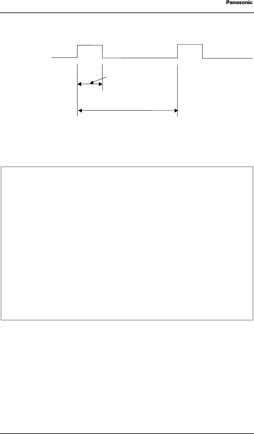
Figure 3 8-bit timer PWM operation timing chart
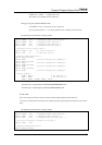
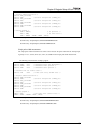
The following section describes a sample program.
/* Control data declaration */
#define
TM4MOD
0x00
/* 0b00000000 Pulse width measurement control (normal timer
operation)*/
#define
TM4PWM
0x10
/* 0b00010000 PWM operation */
#define
TM4EN
0x08
/* 0b00001000 Count operation */
#define
TM4CK
0x02
/* 0b00000010 Use low speed oscillation clock*/
/* 32.768 kHz / 256 = 128 Hz */
/* Determine width for High period of PWM output */
#define
TIME
64 /* 1/4 duty (64/256)*/
/* Register address declaration */
#define
TM4BC_adr
0x3F60
#define
TM4BC
(*(volatile unsigned char *)TM4BC_adr)
#define
TM4OC_adr
0x3F62
#define
TM4OC
(*(volatile unsigned char *)TM4OC_adr)
#define
TM4MD_adr
0x3F64
#define
TM4MD
(*(volatile unsigned char *)TM4MD_adr)
#define
CK4MD_adr
0x3F66
#define
CK4MD
(*(volatile unsigned char *)CK4MD_adr)
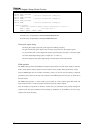
/* Setting program */
TM4OC = TIME;
/* Set pulse width */
TM4MD = TM4MOD | TM4PWM | TM4EN | TM4CK;
This sample is stored in the CD.
Stored directory: Sample\chapter3,4\Initial\ASM\TIMER\PWM\
Stored directory: Sample\chapter3,4\Initial\C\TIMER\PWM\
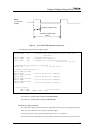
Synchronous output operation
The synchronous output operation provides the output from the port D at the count up timing of the
timer. You can use the timer 1 and 2 for the synchronous output.
You use the port D to set the synchronous output operation. See "3.7.12 Port D".)
You can use the timer setting both in the interval timer mode and event count mode. You can also set
TMxIO
(x is the timer
number)
Compare register value
8-bit timer overflow cycle
128 Hz