


Chapter 3 Register Setup of Each Function
65
20 MHz / 64 = 312500 312500 / 100 = 3125
This setting is not available with the 8-bit timer.
Setting by using
low speed oscillation clock:
32.768 kHz/ 4 = 8192 8192 / 100 = 81.92 = approx. 82
If you set the formula 82 − 1 = 81, the interval timer with 10 milli seconds will be set.
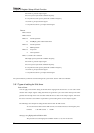
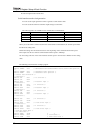
The following section describes a sample program.
/* Control data declaration */
#define
TM0MOD
0x00
/* 0b00000000 Normal timer operation */
#define
TM0PWM
0x00
/* 0b00000000 Timer operation */
#define
TM0EN
0x08
/* 0b00001000 Count operation */
#define
TM0CK
0x01
/* 0b00000001 Prescaler output */
/* Determine time for interval timer */
#define
TM0PSC
0x00
/* 4 division setting */
#define
TIME
81 /* Timer count value */
/* Register address declaration */
#define
TM0BC_adr
0x3F50
#define
TM0BC
(*(volatile unsigned char *)TM0BC_adr)
#define
TM0OC_adr
0x3F52
#define
TM0OC
(*(volatile unsigned char *)TM0OC_adr)
#define
TM0MD_adr
0x3F54
#define
TM0MD
(*(volatile unsigned char *)TM0MD_adr)
#define
CK0MD_adr
0x3F56
#define
CK0MD
(*(volatile unsigned char *)CK0MD_adr)
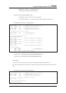
/* Setting program */
CK0MD = TM0PSC;
/* Set prescaler */
TM0OC = TIME;
/* Set timer value */
TM0MD = TM0MOD | TM0PWM | TM0EN | TM0CK;
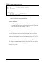
This sample is stored in the CD.
Stored directory: Sample\chapter3,4\Initial\ASM\TIMER\INTERVAL8\
Stored directory: Sample\chapter3,4\Initial\C\TIMER\INTERVAL8\
Event count
The event count uses a binary counter to count an external signal supplied from the timer pin.
You can set a measurement count value to the compare register for generating an interrupt as for the interval
timer.
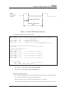
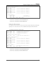
The following section describes a sample program.
/* Control data declaration */
#define TM0CAS 0x00 /* 0b00000000 Normal timer operation */
#define TM0EN 0x08 /* 0b00001000 Count operation */
#define TM0CK 0x06 /* 0b00000110 External input signal */
/* Set value to interrupt, interrupt on 5th signal */
#define COUNT 0x04
/* Register address declaration */
#define TM0BC_adr 0x3F50