


1918
Specifications
Power supply:
DC +12 V (4-pin Cannon Connector)
Power consumption:
DC 12 V, 0.47 A
Video input:
Composite video 1 V [p-p] 75 Ω
a
1
(BNC connector)
Camera control inputs:
Control signal (BNC connector)
a
5
Pan/tilt head control inputs:
Control signal (RJ-45 8-pin modular
jack)
a
5
Preview video outputs:
Composite video 1 V [p-p] 75 Ω
a
5
(BNC connector)
Black burst outputs:
75 Ω
a
6 (BNC connector)
Camera control output:
Control signal (BNC connector)
Pan/tilt head control output:
Control signal (RJ-45 8-pin modular
jack)
Switch function:
Power on/off
Control panel connecting cables:
Number of connecting cables: 4 (3
coaxial cables, 1 10BASE-T straight
cable); 5 sets (when using G/L function)
Pan/tilt head connecting cables:
4 connecting cables per pan/tilt head (3
coaxial cables, 10BASE-T straight
cable)
(when using G/L function)
Maximum cable length:
Length of cable from camera and pan/tilt
head to control panel: Max. 500 m
(assuming: coaxial cable: 5C-2V,
10BASE-T straight cable: UTP category
5)
Operating temperature range:
+14°F to +113°F (–10°C to +45°C)
Dimensions (W
a
H
a
D):
Body:
16
9
/
16
˝
a
3
1
/
2
˝
a
9
7
/
8
˝
(420
a
88
a
250 mm)
Priority switchbox:
2
13
/
16
˝
a
3
1
/
2
˝
a
1
7
/
16
˝
(70
a
88
a
35 mm)
Weight:
Approx. 12.32 lb (5.6 kg)
Finish:
Cover:
Steel panel with AV ivory color
polyvinyl chloride finish (approximate
color: Munsell 7.9Y 6.8/0.8)
Panel:
AV ivory color paint (approximate
color: Munsell 7.9Y 6.8/0.8)
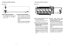
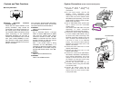
Rack Mounting Example
$
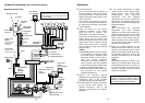
Rack Mounting Procedure
Multi Control Hub
To mount the multi control hub on a rack,
use the supplied rack mounting brackets
and mounting screws (M4
a
10).
1
Press the power switch to turn power
off.
2
Remove the four feet from the bottom of
the multi control hub.
3
Secure the rack mounting brackets to
the sides of the multi control hub using
the supplied mounting screws (
a
4).
4
Mount the multi control hub in the rack
and secure it in place using four rack
mounting screws (part number W2-
MSS/5008).
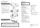
Switchbox
To mount the switchbox on a rack, use the
supplied rack mounting brackets and
mounting screws (M4
a
8).
Power switch
Rack mounting bracket
Rack mounting screws
W2-MSS/5008
(Option)
Mounting screws
Rack mounting bracket
Mounting screws
Feet
<Notes>
O
Rack mounting screws sold separately (part number W2-MSS/5008).
O
To ensure that the temperature within the rack does not exceed +113°F (+45°C), make
sure to provide sufficient space (a minimum of one chassis width between units)
between the multi control hub and the other pieces of equipment mounted in the rack
or install a cooling fan.
Weight and dimensions indicated are
approximate.
Specifications are subject to change
without notice.