


54
For Your Safety
O
Use the dedicated AC adapter (AW-PS505) to supply power to the multi control hub.
O
Handle with care.
The multi control hub may malfunction if it is dropped or exposed to strong shocks.
O
Use within a temperature range of 14°F to 113°F (–10°C to +45°C).
Using the multi control hub in environments colder than 14°F (–10°C) or hotter than
113°F (+45°C) could have a damaging effect on the internal components.
O
Connect and disconnect cables only when the power is turned off.
Make sure to turn the power to the multi control hub off before connecting or
disconnecting cables.
O
Avoid using the multi control hub outdoors.
O
Place the multi control hub a minimum of 1 meter away from monitor video screens.
O
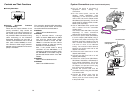
Cleaning
Unplug the multi control hub and wipe it clean using a dry cloth. For dirt that cannot be
removed in this manner, moisten a cloth with kitchen detergent, wring it out thoroughly,
and then wipe gently.
• Never use volatile chemicals such as benzene or paint thinner to clean the multi
control hub.
• Before using chemically treated cloths to clean the multi control hub, read their
instructions and precautions thoroughly.
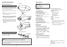
Accessories
O
Priority switchboxes: 5
O
Rack mounting brackets: 12
O
Mounting screws: 24
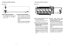
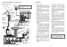
Overview
O
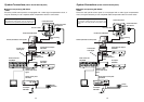
The AW-HB605 multi control hub combines with a system such as the Panasonic AW-
PH300 series indoor pan/tilt head or AW-PH600 series outdoor pan/tilt head to support
the connection of between one and five control panels (AW-RP501, AW-RP301, AW-
RP305) to a single camera and pan/tilt head. Any of the connected control panels may
then be used to control the camera and pan/tilt head (the AW-RP301 and AW-RP305
can control the pan/tilt head only).
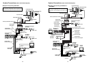
In addition, by adding the AW-HB505 multi port hub and AW-RP505 multi hybrid control
panel, it is possible to construct a system in which between one and five multi hybrid
control panels may be used to control between one and five cameras and pan/tilt heads.
O
When coaxial cable/s (5C-2V) and 10BASE-T (UTP category 5) straight cable/s
(10BASE-T cable only for the AW-RP301 and AW-RP305) are used to make
connections, the distance between the cameras and pan/tilt heads and the control
panels can be extended up to a maximum of 500 meters.
Table of Contents
Overview . . . . . . . . . . . . . . . . . . . . . . . . . 4
Accessories . . . . . . . . . . . . . . . . . . . . . . 4
For Your Safety. . . . . . . . . . . . . . . . . . . . 5
Controls and Their Functions . . . . . . . . 6
$
Front Panel. . . . . . . . . . . . . . . . . . . . 6
$
Rear Panel . . . . . . . . . . . . . . . . . . . . 7
$
Priority Switchbox. . . . . . . . . . . . . . 10
System Connections . . . . . . . . . . . . . . 11
Operations. . . . . . . . . . . . . . . . . . . . . . . 17
Rack Mounting Example . . . . . . . . . . . 18
$
Rack Mounting Procedure . . . . . . . 18
Specifications . . . . . . . . . . . . . . . . . . . . 19