Others
ENGLISH-5554-ENGLISH
Appendix
*1 The “i” appearing after the resolution indicates an interlaced signal.
*2 The following symbols are used to indicate picture quality.
AA Maximum picture quality can be obtained.
A Signals are converted by the image processing circuit before picture
is projected
List of compatible signals
720 x 480i 15.734 59.940 A Video/S-Video
720 x 576i 15.625 50.000 A Video/S-Video
720 x 480i 15.734 59.940 13.500 A YP
BPR
720 x 576i 15.625 50.000 13.500 A YP
BPR
720 x 483 31.469 59.940 27.000 A YP
BPR/DVI
720 x 576 31.250 50.000 27.000 A YPBPR/DVI
1 920 x 1 080i 33.750 60.000 74.250 AA YPBPR/PC/DVI
1 920 x 1 080i 28.125 50.000 74.250 AA YP
BPR/PC/DVI
1 280 x 720 45.000 60.000 74.250 AA YP
BPR/DVI
640 x 480 31.469 59.940 25.175 A PC/DVI
640 x 480 35.000 66.667 30.240 A PC
640 x 480 37.861 72.809 31.500 A PC
640 x 480 37.500 75.000 31.500 A PC
640 x 480 43.269 85.008 36.000 A PC
640 x 480 72.090 138.000 62.284 A PC
856 x 480 30.057 60.114 31.500 A PC/DVI
800 x 600 35.156 56.250 36.000 A PC
800 x 600 37.879 60.317 40.000 A PC/DVI
800 x 600 48.077 72.188 50.000 A PC
800 x 600 46.875 75.000 49.500 A PC
800 x 600 53.674 85.061 56.250 A PC
800 x 600 72.080 112.000 77.849 A PC
1 072 x 600 37.287 59.947 51.382 A PC/DVI
1 280 x 720 45.106 60.141 76.500 AA PC/DVI
1 024 x 768 48.363 60.004 65.000 A PC/DVI
1 024 x 768 56.476 70.069 75.000 A PC
1 024 x 768 60.023 75.029 78.750 A PC
1 024 x 768 68.678 84.997 94.500 A PC
1 024 x 768 72.080 89.000 99.185 A PC
1 280 x 768 45.327 56.518 76.150 A PC/DVI
1 152 x 864 63.995 71.184 94.200 A PC
1 152 x 864 67.500 74.917 108.000 A PC
1 280 x 1 024 63.981 60.020 108.000 A PC/DVI
1 360 x 768 48.830 59.841 73.831 A PC/DVI
Display
resolution
(dots)*
1
Scanning
frequency
H
(kHz)
V
(Hz)
Dot clock
frequency
(MHz)
Picture
quality*
2
NTSC/NTSC4.43/
PAL-M/PAL60
PAL/PAL-N/SECAM
525i
625i
525p
625p
HDTV60
HDTV50
750p
VGA480
WIDE480
SVGA
WIDE600
WIDE720
XGA
WIDE768
MXGA
SXGA
WIDE768-2
FormatMode
Pin No. Signal
#
Earth (Luminance signal)
Earth (Color signal)
Luminance signal
Color signal
$
%
&
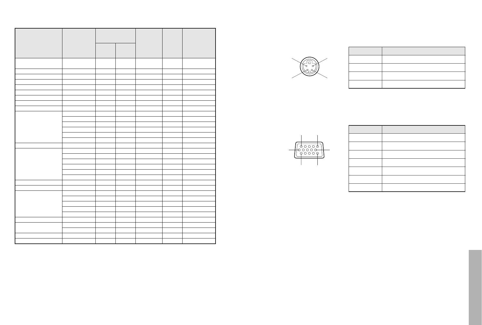
BThe pin layout and signal names for the RGB input connector are shown
below.
Pin No. Signal
#
R
G/G·SYNC
B
SDA
$
%
.
/
HD/SYNC
0
VD
1
SCL
Pin + is spare.
Pins & – *, , and - are for earth.
Pins . and 1 functions are only valid when
supported by the computer
#$
%&
External view
-1
#'
,(
External view
Connector pin wiring
BThe pin layout and signal names for the S-VIDEO input connector are
shown below.


