


12
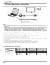
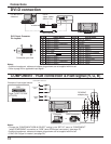
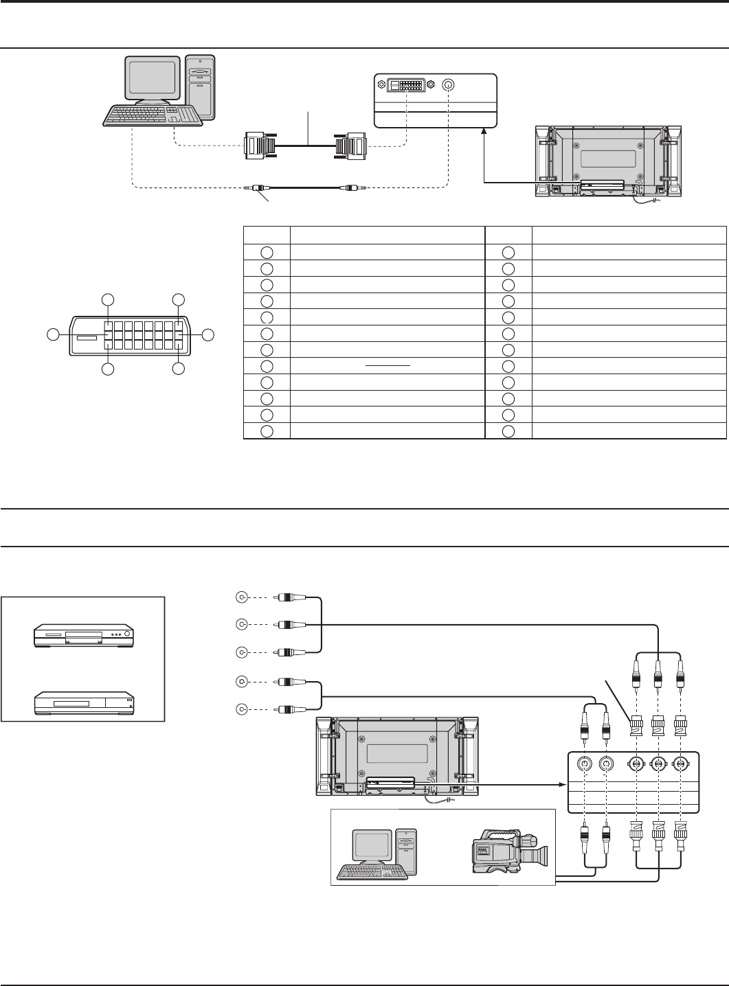
DVI-D connection
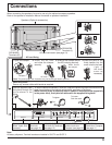
Connections
Notes:
• Additional equipment, cables and adapter plugs shown are not supplied with this set.
• Refer to page 45 for applicable input signal.
Notes:
• Change the “COMPONENT/RGB-IN SELECT” setting in the “SET UP” menu to “COMPONENT”
(when COMPONENT connection) or “RGB” (when RGB signal connection). (see page 37)
• Additional equipment, cables and adapter plugs shown are not supplied with this set.
• SYNC ON G signal is needed. (see page 39)
COMPONENT / RGB connection & RGB signal (R, G, B)
SLOT2
AUDIO
DVI-D IN
Mini-plug (M3)
DVI-D
video cable
(Within 5 m)
PC with DVI-D
video out
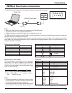
Pin No.
Signal Name
Pin No.
Signal Name
1
T.M.D.S. data 2-
13
T.M.D.S. data 3+
2
T.M.D.S. data 2+
14
+5 V DC
3
T.M.D.S. data 2/4 shielded
15
Ground
4
T.M.D.S. data 4-
16
Hot
plug
sense
5
T.M.D.S. data 4+
17
T.M.D.S. data 0-
6
DDC clock
18
T.M.D.S. data 0+
7
DDC data
19
T.M.D.S. data 0/5 shielded
8
20
T.M.D.S. data 5-
9
T.M.D.S. data 1-
21
T.M.D.S. data 5+
10
T.M.D.S. data 1+
22
T.M.D.S. clock shield
11
T.M.D.S. data 1/3 shielded
23
T.M.D.S. clock+
12
T.M.D.S. data 3-
24
T.M.D.S. clock-
DVI-D Input Connector
Pin Layouts
Connection port view
16
17
24
8
1
9
AUDIO
OUT
Y, P
B, PR,
OUT
R
R
PB
Y
L
R
COMPONENT VIDEO OUT
SLOT3
P
R
/C
R
/R P
B
/C
B
/B
Y/G
AUDIO
RL
COMPONENT/RGB IN
Computer
RGB Camcorder
or
DVD
Example of input signal source
Digital TV-SET-TOP-BOX
(DTV-STB)
RCA-BNC
adapter plug