


3
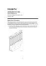
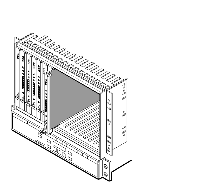
5. Insert the CSU circuit card into the appropriate slot in the carrier. The power-up
self-test begins.
495-1479
7
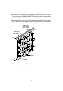
6. If you intend to use front panel emulation, connect the cable from the PC to Port 2
on the Auxiliary Backplane using the COM port adapter and COM-port-to-PC cable.
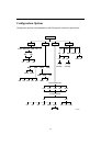
7. The Factory 1 configuration for ESF framing format and B8ZS line coding format is
the default configuration and is appropriate for most networks. If this configuration
does not work for you, try the Factory 2 configuration for D4 framing format and
AMI line coding format. To further customize configuration options, refer to
Changing Configuration Options
in Chapter 3,
Operation
, and Appendix C,
Configuration Options
, in the
ACCULINK 315x Channel Service Unit Operator’s
Guide.
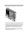
8. During the power-up self-test, the FAIL LED flashes, then all LEDs blink twice.
When the test is complete, verify that the CSU is functional by observing that the
OK, NETWORK SIG, and DTE SIG LEDs are lit.