


6
Connecting the Ethernet Port
The unit provides a single Ethernet interface port for IP Gateway, SNMP, and Web
browser access. This interface is an eight-pin modular jack that complies with standard
twisted-pair, 10/100BaseT requirements.
Procedure
1. Insert one 8-pin connector of your Ethernet cable (not provided) into the
10/100_ETHERNET port.
2. Open the supplied ferrite choke and place it around the Ethernet cable as close to
the 8300 Endpoint as possible. Close the choke and lock it by pressing on the latch.
3. Insert the other end of the cable into the Ethernet interface of your LAN.
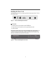
Ethernet LED Indicators
There are two unlabeled indicator LEDs on either side of the 10/100 ETHERNET jack.
The LED on the left side of the jack pulses amber to indicate data activity (either
transmit or receive). The LED on the right side of the jack lights green to indicate that the
link layer is operational.
Connecting the Serial Port
The SERIAL interface port is a multi-protocol interface presented physically as a DB25
connection. The protocols supported by this interface are RS-232, V.35, EIA-530, X.21,
and RS-449. Refer to the user’s guide for pin assignments.
Procedure
1. Connect the DB25 end of your shielded serial cable to the SERIAL port. Secure it
with its captive screws.
2. Attach and secure to the cable any required adapters, such as for a 34-pin V.35
interface.
3. Plug the other end of the cable into your router and fasten it in place.