


5. Diagnostics
5-16 February 2003 8335-A2-GB20-70
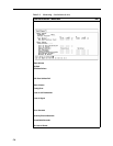
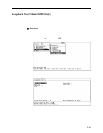
2. Select an interface (dsl1:1 through dsl24:1 on the Model 8385).
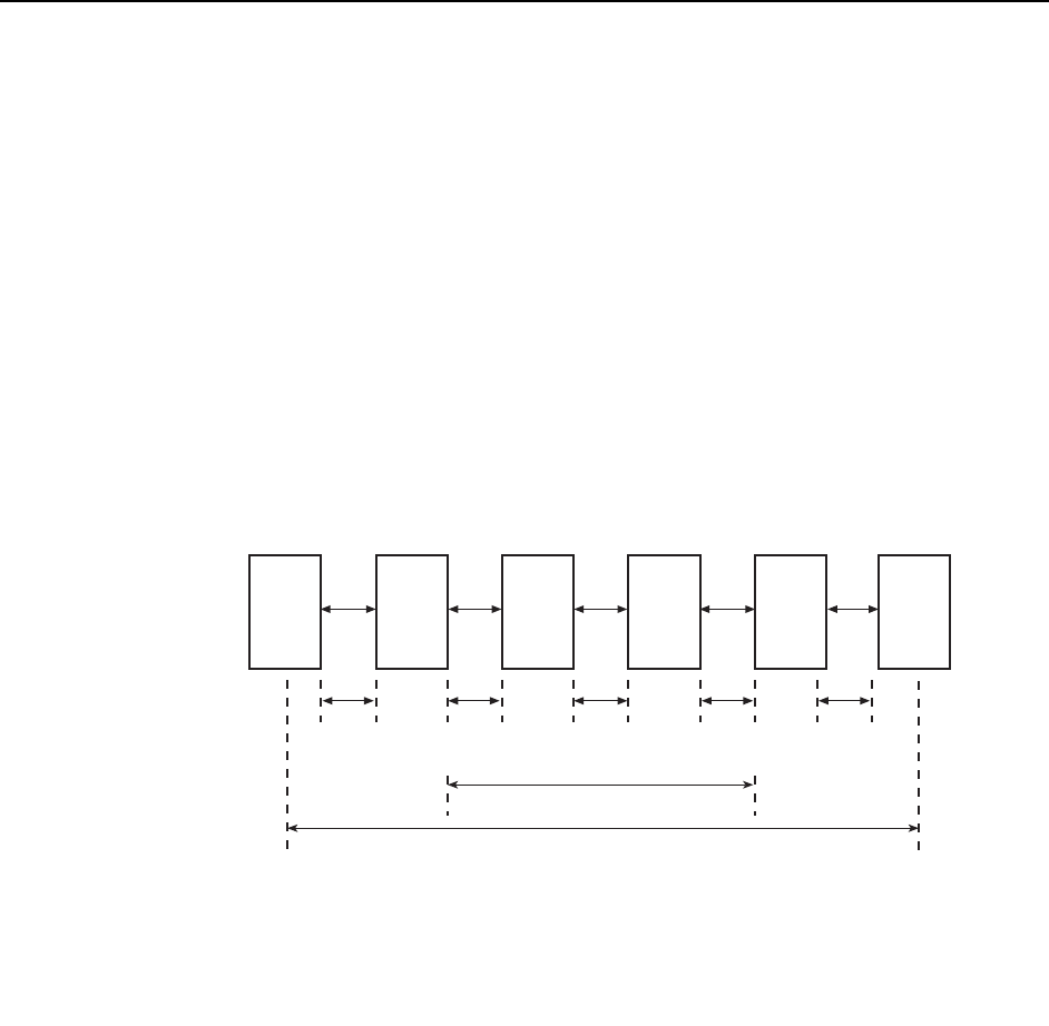
3. Enter the unit to be tested in the SHDSL network segment (STU-C, STU-R, or
SRU1– SRU-8). Use the unit identifiers defined in Figure 5-1, SHDSL Data
Path.
4. Enter the side of the selected unit to be tested (Customer or Network) as
shown in Figure 5-1, SHDSL Data Path.
5. Enter the duration of the test (1–10 minutes).
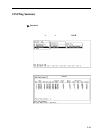
6. Enter Start to start the test. A loopback begins on the selected unit in addition
to a 511 BERT on the STU-C at the same time. The test continues to run until
you enter Stop or the selected duration has expired.
7. Enter Stop if you want to end the test before the duration has expired.
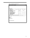
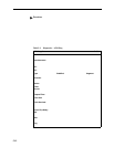
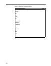
8. Interpret the display as shown in Table 5-5, Diagnostics – Loopback Test.
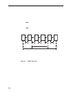
Figure 5-1. SHDSL Data Path
CPE
STU-R
SRU SRU STU-C
NS
CS
SHDSL Span
Application
Specific
SHDSL
Segment
SHDSL
Segment
SHDSL
Segment
Application
Specific
01-17042
User Data Path
PTD
CPE = Customer Premises Equipment
CS = Customer Side
NS = Network Side
PTD = Path Terminating Device
SRU = Signal Regeneration Units
STU-R = SHDSL Transceiver (Remote Terminal Site)
STU-C = SHDSL Transceiver (Centeral Site)
NS
CS
NS
CS