3. Configuration Options
9000-A2-GB31-00 December 2002
3-29
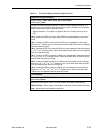
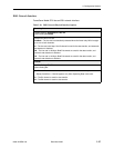
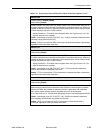
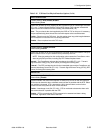
Monitor DSR
Possible Settings: Enable, Disable
Default Setting: Enable
Specifies whether the state of the DCE Ready (DSR) circuit on the network data port will
be used to determine when valid data communication is possible with the unit. When this
condition is detected, an alarm is generated, LMI is declared down, and no further transfer
of frame relay data can occur on this interface.
Display Conditions – This option does not appear when Port Type is set to X.21. The
signal is assumed to be asserted.
Enable – Interchange circuit CC (ITU/CCITT 107) – DSR is monitored to determine when
valid data is being sent from the DCE.
Disable – DSR is not monitored. DSR is assumed to be asserted and data is transmitted,
regardless of the actual state of the lead.
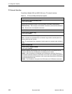
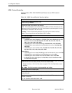
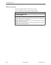
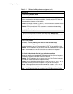
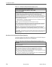
Monitor CTS
Possible Settings: Enable, Disable
Default Setting: Enable
Specifies whether the state of the Clear to Send (CTS) circuit on the network data port will
be used to determine when valid data communication is possible with the unit. When this
condition is detected, an alarm is generated, LMI is declared down, and no further transfer
of frame relay data can occur on this interface.
Display Conditions – This option does not appear when Port Type is set to X.21. The
signal is assumed to be asserted.
Enable – Interchange circuit CB (ITU/CCITT 106) – CTS is monitored to determine
whether data should be transmitted to the DCE.
Disable – CTS is not monitored. CTS is assumed to be asserted and data is transmitted,
regardless of the actual state of the lead.
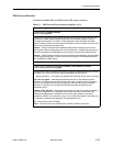
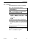
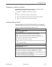
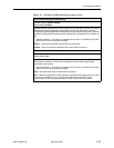
Monitor RLSD
Possible Settings: Enable, Disable
Default Setting: Enable
Specifies whether the state of the Received Line Signal Detector (RLSD) circuit on the
network data port will be used to determine when valid data communication is possible
with the unit. When this condition is detected, an alarm is generated, LMI is declared
down, and no further transfer of frame relay data can occur on this interface.
If Port Type is set to X.21, the Indication interchange circuit is monitored instead of RLSD.
Enable – Interchange circuit CF (ITU/CCITT 109) – RLSD is monitored to determine
when valid data communication is possible with the DCE.
Disable – RLSD is not monitored. RLSD is assumed to be asserted and data is
transmitted, regardless of the actual state of the lead.
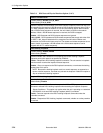
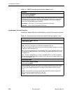
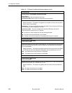
Table 3-13. Synchronous Network Data Port Physical Interface Options (2 of 2)


