


Page 20
3.1.16 256MB SDRAM.
3.1.17 833MHz Freescale processor.
3.1.18 Capable of assigning a unique iSCSI name to each device on the SCSI side
of the bus.
3.1.19 Can automatically obtain an IP address from a DHCP server or the user
can manually assign an IP address, Subnet mask and Gateway to the iSCSI
Protocol Port and Web Port.
3.1.20 Diagnostic web page monitors unit’s boot status.
3.1.21 Diagnostic LEDs for quick and easy unit status.
3.1.22 Modifying the “User Name” and “Password” can customize user login
access.
3.1.23 Hardware override configuration for systems that require a more secure
setup.
3.1.24 Unit can easily be reset to factory default configuration.
3.1.25 Up to 100MB/sec throughput.
3.1.26 The iS520 (Stand-Alone Box version) provides a lockable 5-pin DIN
power connector for added reliability.
3.1.27 Supports One-way and Mutual CHAP security.
3.1.28 Ambient Temperature Shutdown protection.
4. INSTALLATION INSTRUCTIONS
4.1 Installation General. Before you begin installation, make sure all devices on the
SCSI side of the system are powered down, i.e. iS5xx iSCSI Bridge and SCSI
devices (hosts and targets).
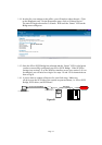
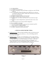
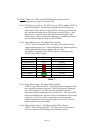
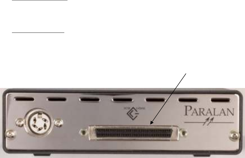
4.2 SCSI Port General. The iS5xx series iSCSI Bridges provide a single SCSI port
for connecting your SCSI devices to your iSCSI network. The SCSI port consists
of a 68-pin High Density “P” SCSI bus connector (see Image 1). Disks, tape
drives, RAID controllers, DVD, MO and CD libraries are supported. Low
Voltage Differential (LVD) transmission mode, Single-Ended (SE) transmission
mode and transfer rates of up to 160 MBYTES/SEC are supported.
Image 1