


Page 23
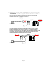
4.5 Connecting SCSI Devices. SCSI cable installation is easy. This installation
assumes the topology in Figure C of section 4.3.
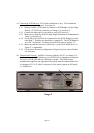
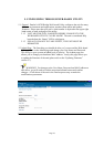
4.5.1 Simply connect a SCSI cable into Paralan’s iSCSI Bridge’s 68-pin High
Density “P” SCSI bus Connector (see Image 1 of section 4.2).
4.5.2 Connect the other end of your cable to your SCSI device(s).
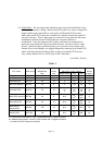
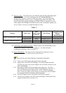
4.5.3 Make sure to abide by the SCSI cable length limitations recommended in
Table 1 of section 4.4.
4.5.4 Set the IDs of the SCSI devices connected to the iSCSI Bridge to a value
other than 7. Each device should have a unique ID. The iSCSI Bridge is
set to ID 7 by default. To change the default ID, refer to section 5.5.
4.5.5 Make sure that the last device on the bus, e.g. the SCSI RAID device in
Figure C, is terminated.
4.5.6 For the more advanced configuration in Figure D please contact Paralan
for assistance.
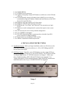
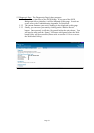
4.6 Ethernet Port General. An RJ45 Connector (labeled “iSCSI”, see Image 2) is
used to connect the iSCSI Bridge to your iSCSI SAN or management computer.
The port is 10/100/1000 Mb/sec, full duplex capable. The Ethernet port
automatically negotiates the appropriate link speed with the connected devices.
A minimum of CAT-5E cable is necessary for the unit to operate at full speed,
i.e. 1000Mb/sec.
Image 2