


CopperLink 1214E Series Quick Start Guide 3
1.0 Configure the DIP Switches
The CL1214E has eight DIP switches (S1) for configuring the unit for a wide variety of
applications. Once the Cl1214E’s are properly installed, they should operate transpar-
ently. No user settings required.
Note Before applying power to the CL1214E, please review section 2.0,
“Power up the CL1214E Series” on page 5 to verify that the unit is con-
nected to the appropriate power source.
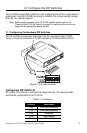
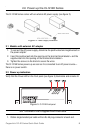
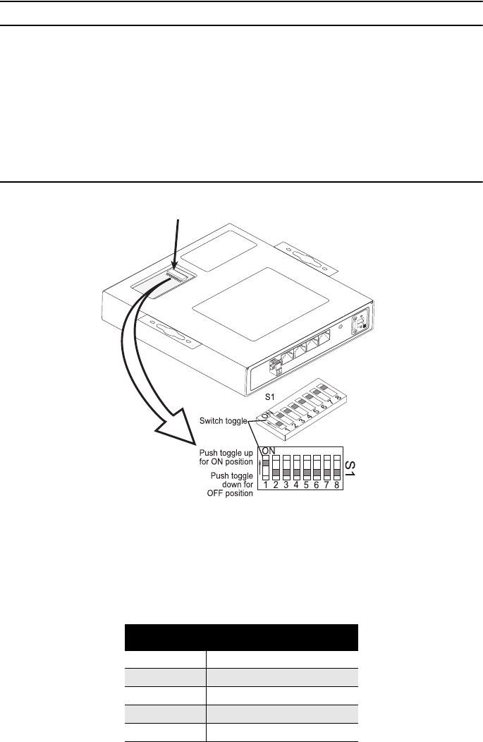
1.1 Configuring the Hardware DIP Switches
The DIP switches are externally accessible from the underside of the CL1214E.
Figure 1 shows the orientation of the DIP switches in the ON and OFF positions.
Figure 1.
DIP switch orientation
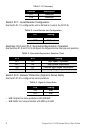
Configuring DIP Switch S1
DIP Switch S1 is where you configure the CopperLink line. The following tables
describe the configuration for the CL1214E.
Table 1.
S1 Summary
Position Description
S1-2 Line Rate/Symmetry
S1-3 Line Rate/Symmetry
S1-4 Reserved
S1-5 SNR Margin
S1-6 Reserved