


6 CopperLink 1214E Series Quick Start Guide
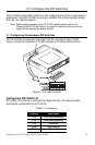
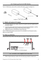
2. Plug one end of the cable into the RJ-45 socket (labeled Line) on the CL1214E.
Verify that the other end of the cable is connected to the Line port on the other
CL1214E and that the port is correctly configured.
3. When a link is established, the Line Link LED will turn on.
4.0 Connect the Ethernet port(s)
The RJ-45 ports labeled Eth 0 through Eth 3 are the Auto-MDIX 10/100Base-T inter-
face. These ports are designed to connect directly to a 10/100Base-T device or network.
You may connect this port to a hub or PC using a straight through or crossover cable
that is up to 328 ft (100 m) long.
5.0 Additional information
For detailed information about installing, configuring, and operating the CopperLink,
refer to the CopperLink 1214E Series User Manual at www.patton.com/manuals/
CL1214E-UM.pdf.
A.0 Compliance Information
A.1 Compliance
EMC:
• EN55022, Class A
• EN55024
Safety:
• IEC/EN60950-1, 2nd edition
PSTN:
• This device is not intended nor approved for connection to the PSTN
1.2 Radio and TV Interference (FCC Part 15)
This equipment generates and uses radio frequency energy, and if not installed and
used properly—that is, in strict accordance with the manufacturer's instructions—may
cause interference to radio and television reception. This equipment has been tested
and found to comply with the limits for a Class A computing device in accordance with
the specifications in Subpart B of Part 15 of FCC rules, which are designed to provide
reasonable protection from such interference in a commercial installation. However,
there is no guarantee that interference will not occur in a particular installation. If the
equipment causes interference to radio or television reception, which can be deter-
mined by disconnecting the cables, try to correct the interference by one or more of the
following measures: moving the computing equipment away from the receiver, re-ori-