


2.0 GENERAL INFORMATION
Thank you for your purchase of this Patton Electronics product.
This product has been thoroughly inspected and tested and is
warranted for One Year parts and labor. If any questions or problems
arise during installation or use of this product, please do not hesitate to
contact Patton Electronics Technical Support at (301) 975-1007.
2.1 FEATURES
• Convenient rack card features two short range modems
• Data rates to 19.2 Kbps
• Full duplex operation
• Supports distances to 17 miles
• Features 13 front panel LEDs
• Silicon Avalanche Diode surge protection
• Fits conveniently in Patton’s rack chassis
• Made in USA
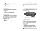
2.2 DESCRIPTION
The Model 1000RC Asynchronous Short Range Modem Rack
Card is a dual rack card incorporating two short range modems. Both
units operate full duplex at data rates to 19.2 Kbps over 2 twisted pairs
and support distances to 17 miles. The Model 1000RC features 13
easy-to-read front panel LEDs, which monitor the status of data
transmission. The Model 1000RC also incorporates Silicon Avalanche
Diodes for protection against the damaging effects of nearby lightning
strikes and other harmful transients.
The Model 1000RC uses the latest surface mount technology to
attain high quality short range modem performance in a convenient
rack card. Filling one function card slot on Patton’s Model 1000R16P
rack chassis, the Model 1000RC is available with RJ-11 or RJ-45 rear
interface cards. For workgroup and desktop communications, the
Model 1000RC also fits in Patton’s 2, 4 and 8 slot Cluster Boxes. The
combination of rack mount, Cluster Box and self-powered units
provides a completely integrated Model 1000 “networking” solution.
3
3.0 CONFIGURATION
This section describes the location and orientation of the Model
1000RC's configuration straps, provides detailed instructions on setting
each strap and describes the settings for each of the rear connection
cards.
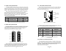
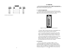
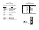
The Model 1000RC uses two sets of configuration straps. These
straps are accessible when the card is slid out of the rack chassis (see
Figure 1, below). Once configured, the Model 1000RC is designed to
operate transparently, without need for frequent re-configuration: just
set it and forget it!
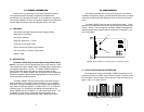
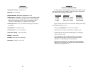
3.1 STRAP LOCATIONS AND ORIENTATION
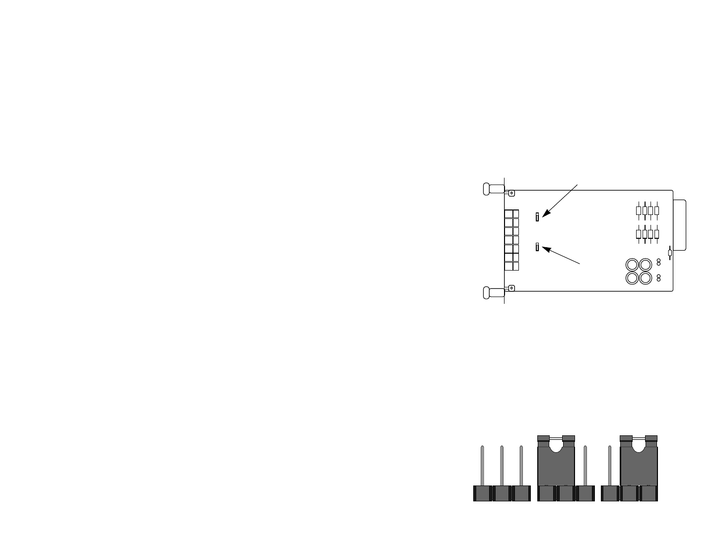
The configuration straps on the Model 1000RC board allow you to
configure the function of both “Carrier Detect” outputs. Figure 2 shows
the orientation of these straps. Notice that each strap can either be on
pegs 1 and 2, or on pegs 2 and 3.
4
Figure 2. Orientation of interface card straps
123 123 123
Figure 1. Model 1000RC card, showing location of configuration jumpers
JP1-A
JP1-B
ON
ON
Normal
Normal
1
2
3
1
2
3