


3.2 FRONT CARD CONFIGURATION
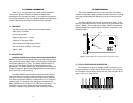
The Model 1000RC contains two sets of configuration straps which
allow you to set the function of “Carrier Detect” output. Since the Model
1000RC contains two modems, each unit can be configured separately:
Jumper 1 (JB1) controls Unit A, while Jumper 2 (JB2) controls Unit B.
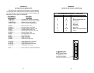
Each “Carrier Detect” strap can be set to “Normal” or “Always on”.
When operating normally, the “CD” LED will blink to indicate the
presence or absence of the carrier. When set to “Always on”, the “CD”
LED will always indicate that the carrier is “ON”. Figure 3 (below)
summarizes the switch settings.
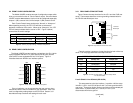
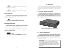
3.3 REAR CARD CONFIGURATION
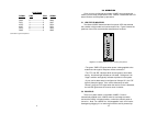
The Model 1000RC has two interface card options: the 1Q11 (which
comes equipped with two RJ-11 ports and two RJ-45 ports) and the
1Q45 (which comes equipped with four RJ-45 ports). Figure 4
illustrates these two different rear interface options.
Prior to installation, you should examine the rear card you have
selected and ensure that it is suitable for your application. Each rear
card is configured by setting straps on the PC board. Section 3.3.1
describes the strap locations and settings for each card.
5
INTERFACE CARD JUMPER SUMMARY TABLE #1
Jumper Function Position 1&2 Position 2&3
JP1-A Carrier Detect - Unit A Always ON* Normal
JP1-B Carrier Detect - Unit B Always ON* Normal
Figure 3. Summary of jumper settings, *indicates factory default
Figure 4. Model 1000RC rear interface card options
RJ-11/6
RJ-45/10
1Q45
1Q11
RJ-11/6
RJ-45/10
RJ-45/10
RJ-45/10
RJ-45/10
RJ-45/10
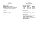
3.3.1 REAR CARD STRAP SETTINGS
Figure 5 shows the strap locations for the 1Q11 and the 1Q45 rear
cards. These straps determine various grounding characteristics for
the RS-232 and twisted pair lines.
Figure 6 provides a summary of strap functions for both of the rear
cards. The next page describes each strap's function.
Line A Shield & Line B Shield (JB2 & JB4)
This strap pertains to the line interface. In position 1&2, the strap
links RJ-11 pins 1 and 6 (RJ-45 pins 2 and 7) to frame ground and the
rear panel. These pins can be used as connections for the twisted pair
cable shield. In position 2&3, pins 1 and 6 (or 2 and 7) are
disconnected from frame ground.
(continued)
6
Strap Position 1&2 Position 2&3
JB2 Line A Shield No Shield
†
JB4 Line B Shield No Shield
†
JB5 SGND & FRGND* Open (Not Connected)
†
JB6 Unit A DSR
†
N/A
JB7 Unit B DSR
†
N/A
INTERFACE CARD STRAP SUMMARY TABLE #1
Figure 6. Summary of strap settings,
†
indicates factory default
*via 100 ohm resistor
Figure 5. Strap locations for both rear cards
1
2
3
1
2
3
1
2
3
1
2
3
123
(Unit A)
JB2
JB4
JB6
JB7
JB5
(Unit B)
(Unit A)
(Unit B)
Converter
twisted pair
Terminal
}
}