


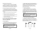

RJ-45 Cable
SIGNAL PIN# PIN# SIGNAL
GND
†
2-----------------------7 GND
†
RCV- 3-----------------------5 XMT-
XMT+ 4-----------------------6 RCV+
XMT- 5-----------------------3 RCV-
RCV+ 6-----------------------4 XMT+
GND
†
7-----------------------2 GND
†
†
Connection to ground is optional
11
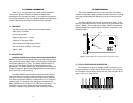
5.0 OPERATION
Once you have configured each Model 1000RC and connected the
cables, you are ready to operate the units. Section 5.0 describes the LED
status monitors and the power-up procedure.
5.1 LED STATUS MONITORS
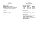
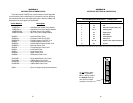
The Model 1000RC features thirteen front panel LEDs that indicate
the condition of the modem and communication link. Figure 9 shows the
positions of the LEDs and the bullets describe their functions.
• The green “PWR” LED glows when power is being applied to the
modem card through its mid-plane chassis connection.
• The “TD” and “RD” indicators blink red and green to show data
activity. A solid red light indicates an idle state. Solid green is an
“illegal” condition and typically indicates a problem in the system.
• If your carrier detect strap is configured as “Always On”, the “CD”
light will always be green. If the carrier detect strap is set to
“Normal”, the green LED lights when the receive carrier is detected;
the red LED lights when the receive carrier is absent.
5.2 POWER-UP
There is no power switch on the Model 1000RC: Power is
automatically applied to the 1000RC when its card-edge connector
touches the chassis’ mid-plane socket, or when the chassis’ power is
turned on.
Note: The 1000RC is a “hot swappable” card—it will not be
damaged by plugging it in or removing it while the rack is powered up.
12
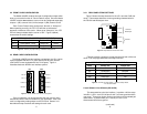
Figure 9. The Model 1000RC front panel, showing LED positions
Model 1000RC
Power
TD
RD
CD
TD
RD
CD
Unit
A
Unit
B