


2.0 GENERAL INFORMATION
Thank you for your purchase of this Patton Electronics product.
This product has been thoroughly inspected and tested and is
warranted for One Year parts and labor. If any questions or problems
arise during installation or use of this product, please do not hesitate to
contact Patton Electronics Technical Support at (301) 975-1007.
2.1 FEATURES
•Full duplex operation on coax or a single twisted pair
•Data rates to 19,200 bps
• Range to 2 miles (3.2 km)
• No AC power or batteries required
• Twisted pair connection via strain relief, RJ-11 or RJ-45
• Surge protected (Model 1000S only)
• Coax connection via female BNC (optional)
• External DCE/DTE switch
• Made in the USA
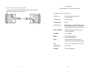
2.2 DESCRIPTION
The Model 1002 Asynchronous Short Range Modemextends
RS-232 distances to 2 miles (3.2 km) over coax or a single
unconditioned twisted pair. The small size of this unit enables use
where serial ports are very close together or are not easily accessible.
The Model 1002 incorporates innovative circuitry that lets it operate
without connection to AC power or batteries. The necessary power for
operation is derived from the RS-232 input signals.
An external DCE/DTE switch allows easy connection of the Model
1002 to any device without opening the unit to re-configure. Three
enclosure options allow termination of a single twisted pair via RJ-11,
RJ-45 or terminal blocks. A unique strain relief prevents the twisted
pair from breaking or pulling loose. An additional enclosure option
allows termination of coax cable via female BNC.
The Model 1002S is a surge protected version of the Model 1002
that uses the latest in bi-directional, clamping, transient suppressors to
protect itself and connected equipment against harmful transient
discharges. For surge handling capability, the Model 1002S is
compliant with IEC 801.5 level 2, 1kV.
3
3.0 INSTALLATION
The Patton Model 1002 is easy to install and should give you
years of trouble-free service. You must have a PAIR of units to perform
an installation—one at each end of an unconditioned twisted pair or
coax cable. The following instructions explain this procedure.
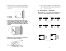
3.1 SETTING THE DTE/DCE SWITCH
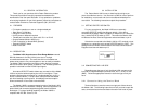
For your convenience, the Model 1002 has an externally
accessible DCE/DTE switch (see diagram below). If the device
connected to the Model 1002 is a modem or multiplexer (or is wired like
one), set the DCE/DTE switch to “DTE”. This means the Model 1002
will behave like Data Terminal Equipment and transmit data on pin 2.
If the device connected to the Model 1002 is a PC, terminal or host
computer (or is wired like one), set the DCE/DTE switch to "DCE". This
setting means the Model 1002 will behave like Data Communications
Equipment and transmit data on pin 3.
3.2 CONNECTING THE LINE SIDE
Depending upon the type of unit, the Model 1002 connects to the
line side via single twisted pair (terminal block, RJ-11, RJ-45) or coax
(BNC). Follow the appropriate instruction set for the type of unit you
have.
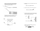
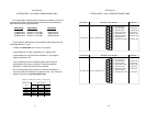
3.2.1 Connection Using the Terminal Block
Terminal blocks are used to connect a single pair of bare wires to
the Model 1002. The following instructions will tell you how to open the
case, connect the bare wires and fasten the strain relief collar in place.
4
DCE
DTE