


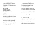
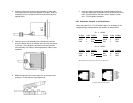
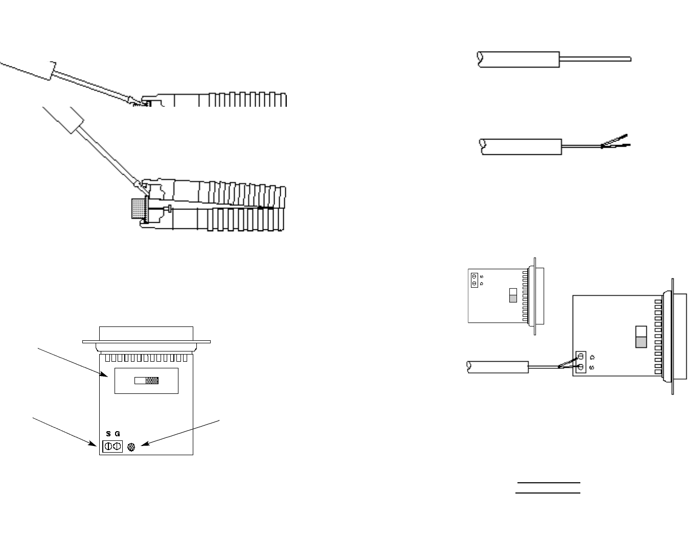
1. Open the unit by gently inserting a screwdriver between the
DB-25 connector and the lip of the plastic case (see below).
You don't have to worry about breaking the plastic, but be
careful not to bend the D-sub connector.
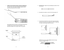
Having opened the unit's case, you will find the terminal block
mounted at the rear of the PC board (see below). The
terminals are labled “S” for “signal” and “G” for “ground“.
5
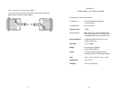
2. Strip the outer insulation from the twisted pairs about one inch
from the end.
3. Strip back the insulation on each of the 2 wires about .25”.
4. Insert the two wire data line to the center (signal) and shield
(ground) terminal posts, then tighten the screws. Depending
on version, terminal post locations may vary.
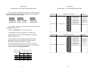
NOTE: Be sure that all cabling between the short range
modems is straight through:
SIGNAL (S) (S) SIGNAL
GROUND (G) (G) GROUND
6
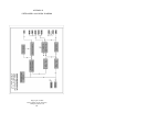
DCE/DTE
Switch
Surge
Suppressors
(1002S only)
Terminal
Block