


CRC
9 pulses = Detected LAN receive frame(s) too
large
10 pulses = Detected LAN receive frame(s) not
octet aligned
11 pulses = Detected LAN receive frame(s) with
bad CRC
10BT Link (Active Green) Solid green indicates that the
10BaseT Ethernet interface has detected a valid
SQE heartbeat, signifying a valid 10BaseT con-
nection.
NS (Active Red) Solid red indicates that the Digital
Signal Processors (DSPs) are not linked.
ER (Active Red) Flashing red indicates CRC Errors on
DSL (Framer) side if DSL Link is active or if bit
errors are received during loop/BER test.
- ER flashes once to indicate a CRC error (during
normal operation) or bit errors (during Remote
Loopback 511/511E tests).
TM (Active Yellow) Solid Yellow indicates an Active
Test Mode. The unit may be placed in test mode
by the local user or by the remote user.
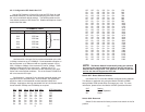
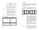
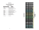
6.3 LED STATUS TABLE
LOCAL REMOTE
10BaseT DSL Status NS ER TM 10Base-T DSL Status NS ER TM
Power ON G* off F ON off off G* off F ON off off
DSL Link G* G F off off off G* off F off off off
Link Brk G* off F off off off G* off F off off off
Brk+ 10s G* off F ON off off G* off F ON off off
RDL G* G F off off ON G* off F off off ON
RDL+511 G* off F off off ON G* off F off off ON
With DTE Connected With DTE Connected
Mark G* G F off off off G* G F off off off
Space G* G F off off off G* G F off off off
Data G* G F off off off G* G F off off off
Link Brk = DSL Link Broken
Brk+10s = 10 Seconds following Link Break
G=GREEN
O=ORANGE
ON= ON
off= OFF
F=Flashing
G*=Green if a valid 10Base-T connection is detected.
17
6.4 TEST MODES
The Model 1088 offers a proprietary Remote Loopback test modes,
plus a built-in V.52 BER test pattern generator to evaluate the communi-
cation status between units. Activate this test mode by toggling the Test
Mode Switch on the front panel of the unit.
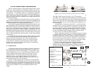
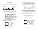
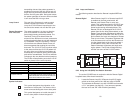
6.4.1 Overview
Figure 10 below shows the major elements used in the loop-back
and 511 pattern tests available in the Model 1088. Each block has sever-
al functions. Following Figure 10 are descriptions of the elements during
Test Modes.
Framer The framer determines the status of the line. In
normal operation the framer transmits and expects
to receive framed packets from the far end. If the
framer receives framed packets from the far end,
the DSL Link LED will turn on. If framed packets
are not received, the DSL Link LED will turn off.
The restart procedure uses this information to
determine if a valid connection is made (cable dis-
connect, poor cable quality, etc). In normal Data
Mode, if the box receives 4 seconds of unframed
packets it will restart the box and begin trying to
re-establish a connection
with the the remote Model 1088. The distinction
between framed packets and unframed packets
becomes important when we discuss the Pattern
Generator.
Pattern Gen/Det This part of the Processor generates and detects
the 511/511E patterns. When transmitting 511 pat-
terns, the information is unframed (because it origi-
nates after the framer) and is intended to be evalu-
ated only by another Processor. If the units are
18
Pattern
Gen/Det
Loop
Contr
ol
Loop
Contro
l
Pattern
Gen/Det
Processor
Processor
Framer
Framer
DSL
Span
Figure 10: Block Diagram- Two Model 1088s Communicating Over the DSL Span