2. If the above test indicates no errors are present, move the
test switch V.52 toggle switch UP, activating the “511/E”
test with intentional errors present. If the test is working prop
erly, the local unit’s red “ER” LED will blink. A successful
“511/E” test will confirm that the link is in place, and that the
Model 1088’s built-in “511” generator and detector are work
ing properly.
21
APPENDIX A
PATTON ELECTRONICS 10BASE-T MDSL ROCKET
SPECIFICATIONS
Clocking Modes:
Internal or Receive Recovered
DTE Rate: All 64k increments from 64 to 2304 kbps
Diagnostics: V52 compliant (511/511E) pattern generator
and detector with error injection mode and
Remote Loopback control by a single front
panel switch
LED Status: The following LEDs are displayed on the
front panel:
DSL Link (Green Active) - DSL Link Active
10BT Link (Green Active) - Valid Ethernet
Connection
Status (Flashing Yellow) - Status indica-
tion from the Ethernet port
NS (Red Active) - No signal on DSP Link
ER (Flashing Red) - CRC error during nor-
mal operation, bit error during pattern gen-
eration test
TM (Active Yellow) - Test Mode Enabled
Configuration: Externally accessible dip switches or
SNMP/HTTP managed through 1095RC
Power: +5V External desk top power supply, 100-
240VAC, 50-60 Hz (Universal Input), 10W
or -48 VDC
Compliance: FCC Part 15, CE mark
Transmission Line: Single Twisted Pair (2 wires)
Line Coding: CAP (Carrierless Amplitude and Phase
Modulation)
Line Rates (DSL line): 144, 272, 400, 528, 784, 1040, 1552, 2064,
2320 kbps
Line Interface: Transformer coupled, 1500 VAC isolation
mDSL Physical
ETHERNET SPECIFICATIONS
Connection:
RJ-45, 10Base-T 802.3 Ethernet
Protocol: PPP (RFC 1661) with Bridging Control
(RFC 1638)
Address Aging: Entries are deleted after 8 minutes of inac-
tivity
Frame Latency: 1 Frame
Frame Buffer: 512 Frames
Ethernet Physical
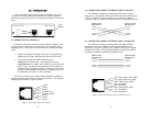
Connection:
pin 1 TD Data +
pin 2 TD Data -
pin 3 RD Data +
pin 6 RD Data +
pins 4, 5, 7, 8 no connection
22


