


Signal/Pin Assignments
The 6-wire RJ-11 and 8-wire RJ-45 jack options for the Model
1012B are prewired for a standard TELCO wiring environment. Use the
guide below when ordering or constructing twisted pair cables.
RJ-11 SIGNAL RJ-45 SIGNAL
1 . . . . . .GND† 1 . . . . . . .N/C
2 . . . . . .RCV- 2 . . . . . .GND†
3 . . . . . .XMT+ 3 . . . . . . .RCV-
4 . . . . . .XMT- 4 . . . . . .XMT+
5 . . . . . .RCV+ 5 . . . . . . .XMT-
6 . . . . . .GND† 6 . . . . . .RCV+
7 . . . . . .GND†
8 . . . . . . .N/C
†
Connection to ground is optional
Crossover Cable Construction
Connection of a 4-wire twisted pair circuit between two or more
Model 1012Bs requires a crossover cable as shown in the figures on
the following page.
RJ-11
SIGNAL PIN# PIN# . . . . . . . . . . .SIGNAL
GND† 1 6 . . . . . . . . . . . . .GND†
RCV- 2 4 . . . . . . . . . . . . . .XMT-
XMT+ 3 5 . . . . . . . . . . . . .RCV+
XMT- 4 2 . . . . . . . . . . . . . .RCV-
RCV+ 5 3 . . . . . . . . . . . . .XMT+
GND† 6 1 . . . . . . . . . . . . .GND†
RJ-45
SIGNAL PIN# PIN# . . . . . . . . . . .SIGNAL
GND† 2 7 . . . . . . . . . . . . .GND†
RCV- 3 5 . . . . . . . . . . . . . .XMT-
XMT+ 4 6 . . . . . . . . . . . . .RCV+
XMT- 5 3 . . . . . . . . . . . . . .RCV-
RCV+ 6 4 . . . . . . . . . . . . .XMT+
GND† 7 2 . . . . . . . . . . . . .GND†
†
Connection to ground is optional
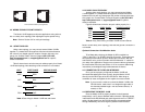
3. Connect one pair of wires to XMT+ and XMT- (transmit positive
and negative) on the terminal block, making careful note of
which color is positive, and which color is negative.
4. Connect the other pair of wires to RCV+ and RCV- (receive
positive and negative) on the terminal block, again making
careful note of which color is positive, and which color is
negative. Your completed crossover cable should be pinned
electrically as shown below:
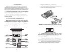
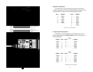
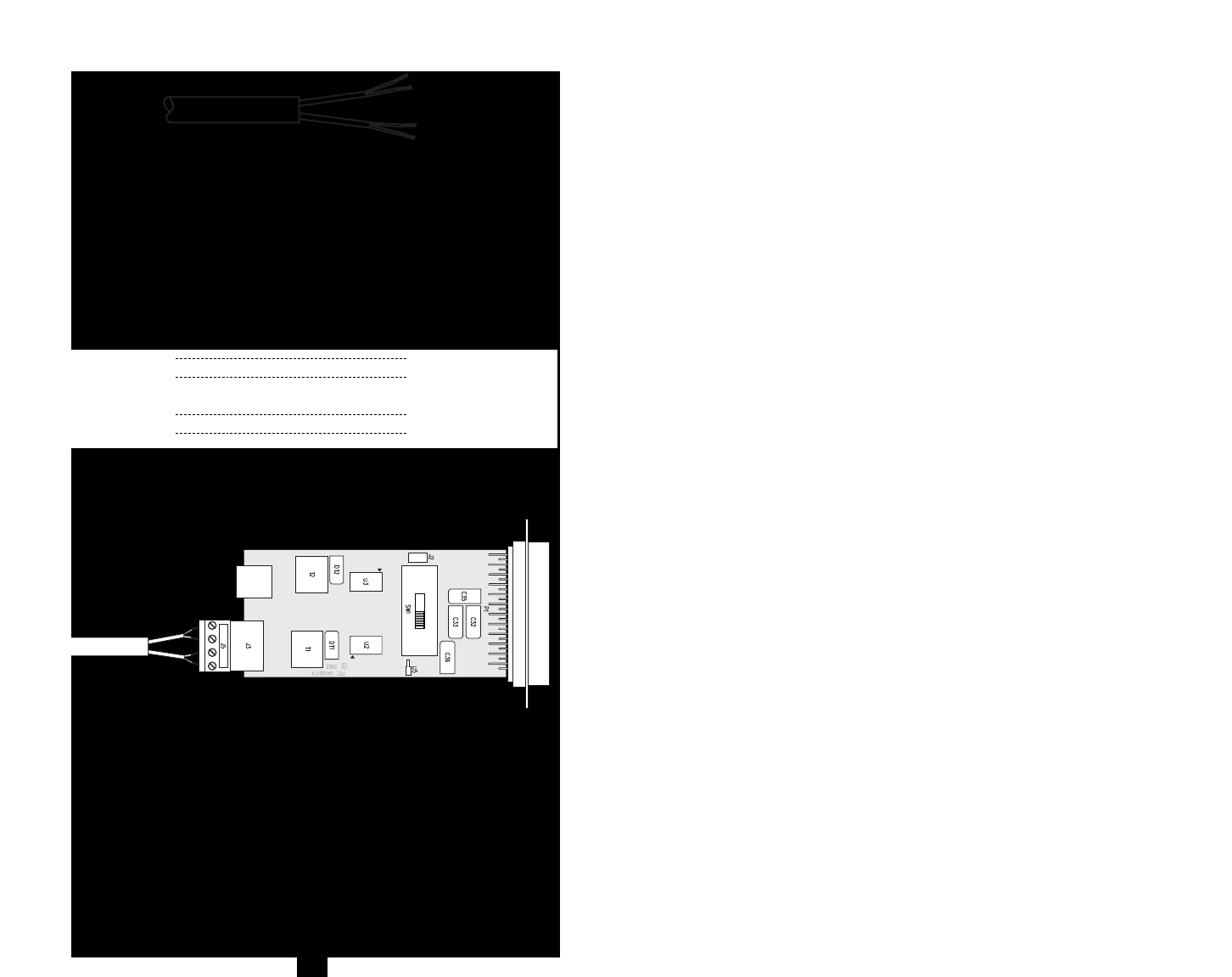
5. When you finish connecting the wires to the terminal block, the
assembly should resemble the diagram Figure 6 below.
The Model 1012B is now installed.
4.1.2 MODULAR TWISTED PAIR CONNECTION
The Model 1012B offers two interface options for twisted pair
connection: RJ-11 (6-wire) jack and RJ-45 (8-wire) jack. Pages 9 and
10 show signal/pin assignments for the jacks, as well as pin-outs for the
appropriate twisted pair cable topologies.
XMT + RCV+
XMT - RCV -
RCV - XMT -
RCV + XMT+
}
One Pair
}
One Pair
7
Figure 5. Stripping 0.25-inch of insulation from the twisted pairs
Figure 6. Wiring terminal block of Model 1012B
8