


12
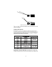
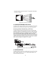
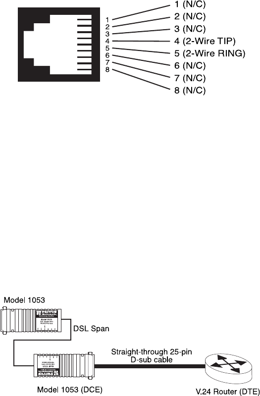
tive and is wired for a two-wire interface. The signal/pin relationships
are shown in Figure 4.
Figure 4.
Model 1053 twisted pair line interface
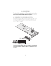
4.2 CONNECTING THE MODEL 1053/A (RS-232)
The Model 1053/A supports RS-232 serial port connections. This section
describes how to connect the serial ports to your RS-232 equipment.
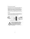
Connecting the Model 1053/A (RS-232) to a DTE Device
The Model 1053/A provides an RS-232 DCE (data circuit terminating
equipment) interface on a DB-25 female connector. As a DCE, this inter-
face is designed to connect to DTE equipment, such as a router. When
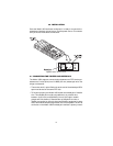
connecting the RS-232 interface of the Model 1053/A to your DTE
device, use an RS-232 straight-through cable (see Figure 5). Appendix C
on page 18 describes pin assignments and signal sources for the Model
1053/A RS-232 interface. When purchasing or constructing an interface
cable, use the pin diagrams in Appendix C as a guide.
Figure 5.
Connecting the Model 1053/A to an RS-232 serial DTE
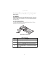
4.3 POWER CONNECTION
The Model 1053 (all versions) are available with Universal AC (100–240
VAC), 120 VAC, 230 VAC or -12, -24, or -48 VDC power options. This
section describes these options.