


7
3.0 CONFIGURATION
The Model 1053 is equipped with 16 DIP switches that enable configura-
tion of the unit for a wide variety of applications. This section describes
switch locations and explains the different configurations
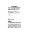
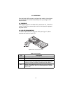
3.1 CONFIGURING THE HARDWARE DIP SWITCHES
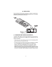
S1 and S2 each contain eight internal DIP switches (see Figure 1) that
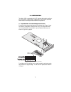
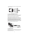
are used for configuration reset purposes only. To access switch sets,
use a small flat blade screwdriver to open the Model 1053’s case as
shown in Figure 2 on page 8.
Figure 1.
DIP switches S1 and S2
To configure the DIP switches, use a small screwdriver and gently push
each switch to its proper setting. The ON and OFF positions are shown
in Figure 1.