


16
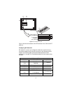
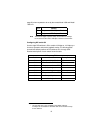
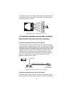
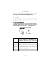
The RJ-45 connector on the Model 1082’s twisted pair interface is polar-
ity insensitive and is wired for a two-wire interface. The signal/pin rela-
tionships are shown in Figure 5.
Figure 5.
Model 1082 RJ-45 twisted pair line interface
4.2 CONNECTING THE MODEL 1082 (V.35) SERIAL INTERFACE
Model 1082 supports V.35 serial port connections. This section
describes how to connect the serial ports to your V.35 equipment.
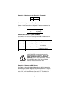
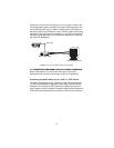
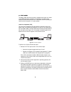
Connecting the Model 1082 (V.35) to a DTE Device
The Model 1082 provides a V.35 DCE (Data Circuit Terminating Equip-
ment) interface on an M/34 female connector. As a DCE, this interface is
designed to connect to DTE equipment, such as a router. When connect-
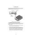
ing the V.35 interface of the Model 1082 to your DTE device, use a V.35
straight-through cable (see Figure 6). Appendix C, “Model 1082C and
1082D Interface Pin Assignments” on page 28 describes pin assign-
ments and signal sources for the Model 1082 V.35 interface. When pur-
chasing or constructing an interface cable, please refer to the pin
diagrams in Appendix C as a guide.
Figure 6.
Connecting the Model 1082 to a V.35 serial DTE
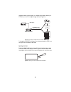
Connecting the Model 1082 (V.35) to a DCE Device
The Model 1082 provides a V.35 DCE (Data Circuit Terminating Equip-
ment) interface on an M/34 female connector. As a DCE, this interface is
V.35 Router (DTE)
Model 1082 (DCE)
Model 1082
Straight-through M/34 cable
DSL Span