


8
3.0 CONFIGURATION
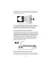
The Model 1082 and 1082/144 each are equipped with 16 DIP switches
that enable configuration of the unit for a wide variety of applications.
This section describes switch locations and explains the different config-
urations
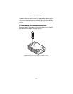
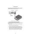
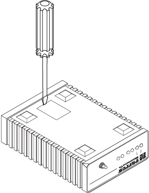
3.1 CONFIGURING THE HARDWARE DIP SWITCHES
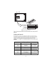
Using a small flat-tip screwdriver, remove the protective cover located on
the underside of the Model 1092 (see Figure 2).
Figure 2.
Removing the cover to access DIP switches S1 and S2
511
G.703/G.704 Test Modes
511E
Model 1194E Single Mode Fiber - Quad G.703/G.704 Modem
511/RDL
TMER
NSStatus
NetLink 10BastT iDSL Modem
10BTDSL
Normal
511E/RBL
Link