


21
5.0 OPERATION
Once the Model 1082 is properly configured and installed, it should oper-
ate transparently. This sections describes power-up, reading the LED
status monitors, and using the built-in loopback test modes.
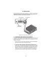
5.1 POWER-UP
To apply power to the Model 1082, first be sure that you have read “Con-
necting Power” on page 19, and that the unit is connected to the appro-
priate power source. Then power-up the unit.
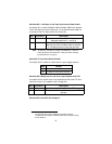
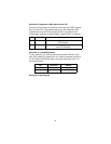
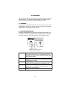
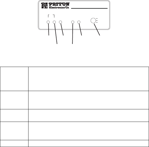
5.2 LED STATUS MONITORS
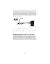
The Model 1082 features six front panel LEDs that monitor power, the
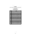
DTE signals, network connection and test modes. Figure 12 shows the
front panel location of each LED. See also, LED description Table 1.
Figure 12. Model 1082 front panel
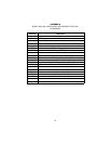
Table 1: LED descriptions
DSL Link (Active Green) Solid green (On) indicates that the end
to end DSL Framer Link is up, signifying that the link
across the DSL span is active. The DSL Link LED is Off
when the link is down.
TD & RD Glows yellow to indicate an idle condition of Binary “1”
data on the respective terminal interface signals. Green
indicates Binary “0” data
NS (No Signal) glows red to indicate that the local Model
1082 is not connected with the remote Model 1082.
ER Blinks ON/OFF after a 511/511E test has timed out.
See “Using the V.52 (BER) test pattern generator” on
page 24 for more information.
TM Glows yellow to indicate TM
DSL
NetLink™ 10Base-T iDSL Model
10BT NS ER TM
Link
511E/RDL
Normal
511/RDL
DSL NS
10BT
TM
ER
Loopback
switch