


12
3.0 CONFIGURATION
The Model 1082/F is equipped with 8 DIP switches that enable configu-
ration of the unit for a variety of applications. This section describes
switch locations and explains the different configurations.
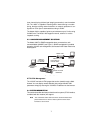
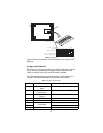
3.1 CONFIGURING THE HARDWARE DIP SWITCHES
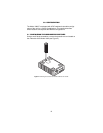
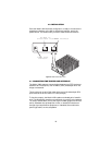
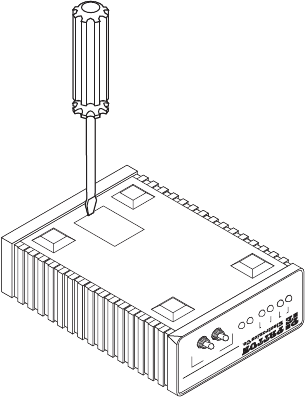
Using a small flat-tip screwdriver, remove the protective cover located on
the underside of the Model 1082 (see Figure 4).
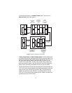
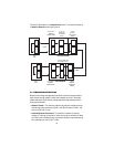
Figure 4.
Removing the cover to access DIP switches S1 and S2
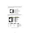
TMER
NS
LOS
NetLink 64K/G.703 iDSL Modem
G.703DSL
Link
Status
Test Modes
511/RDL
Normal
511E
Remote
Normal
Local