


23
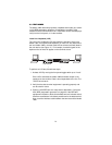
Using the V.52 (BER) test pattern generator
To use the V.52 BER tests in conjunction with the Remote Digital Loop-
back tests (or with Local Line Loopback tests), do the following:
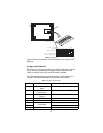
1. Locate the 511/511E toggle switch on the front panel of the Model
1082 and set the toggle to the down position. This activates the V.52
BER test mode and transmits a 511 test pattern into the loop. If any
errors are present, the local modem’s red ER LED will blink continu-
ously.
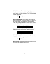
2. If the above test indicates that no errors are present, move the V.52
toggle switch to the up position, activating the 511/E test with errors
present. If the test is working properly, the local modem’s red ER
LED will blink. A successful 511/E test will confirm that the link is in
place, and that the Model 1082’s built-in 511 generator and detector
are working properly.