


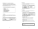
5.0 OPERATION
Once the Model 1092ARC is properly configured and installed, it
should operate transparently. This sections describes functions of the
LED status indicators, and the use of the built-in loopback test modes.
5.1 LED STATUS INDICATORS
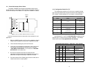
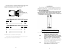
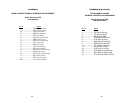
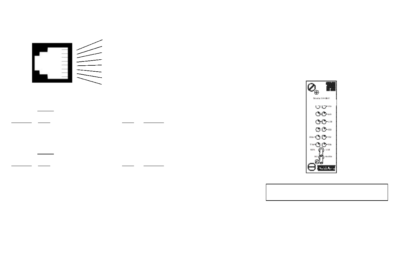
The Model 1092ARC features twelve front panel LEDs that monitor
power, the DTE signals, network connection and test modes. Figure
11(below) shows the front panel location of each LED. Following Figure
11 is a description of each LED function.
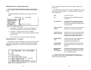
TD & RD glow yellow to indicate an idle condition of Binary
“1” data on the respective terminal interface
signals. Green indicates Binary “0” data.
CTS consists of 2 LEDs, 1 yellow, 1 green. CTS glows
green to indicate that the Clear to Send signal from
the modem is active. Yellow indicates inactive
CTS.
CD consists of 2 LEDs, 1 yellow, 1 green. CD glows
yellow if no carrier signal is being received from the
remote modem. Green indicates that the remote
modem’s carrier is being received.
DTR glows green to indicate that the Data Terminal
Ready signal from the terminal is active.
30
Figure 11.The Model 1092ARC Series' front panel LEDs
Model 1092ARC
Note: LEDs described as yellow are red in earlier
versions of the 1092ARC.
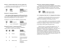
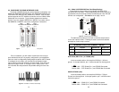
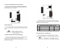
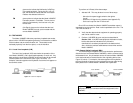
The RJ-45 connector on the Model 1092ARC’s twisted pair interface
is polarity insensitive and is wired for a two-wire interface. The
signal/pin relationships are shown in Figure 9 below.
3. Proper 2-Wire
Pairingbetween the two modems is as follows:
SIGNAL
PIN# PIN# SIGNAL
TIP 4---------------------------------------------4 TIP
RING 5---------------------------------------------5 RING
4. Proper 4-Wire
Pairing between the two modems is as follows:
SIGNAL
PIN# PIN# SIGNAL
Tx 4---------------------------------------------3 Rx
Tx 5---------------------------------------------6 Rx
Rx 3---------------------------------------------4 Tx
Rx 6---------------------------------------------5 Tx
4.3.4 Connection to the Control Port Interface
Please refer to the Model 1001CC Control Card user manual for
cable requirements of the Control Port Interface.
29
Figure 10.Model 1092ARC twisted pair lineinterface.
1 (N/C)
2 (GND)
3 (4-Wire Rx)
4 (2-Wire TIP/4-Wire Tx)
5 (2-Wire RING/4-Wire Tx)
6 (4-Wire Rx)
7 (GND)
8 (N/C)
1
2
3
4
5
6
7
8