


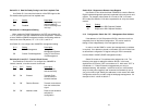

Switch S5-2: 2-Wire/4-Wire
Use Switch S5-2 to configure 2-Wire or 4-Wire operation.
S5-2
Setting Description
Off 2-Wire 2-Wire Operation
On 4-Wire 4-Wire Operation
Switch S5-3: Enable LAL and RDL from DTE
Use Switch S5-3 to enable or disable the Local Analog Loopback
and Remote Digital Loopback control from the DTE.
S5-3
Setting Description
On Enabled LAL and RDL enabled
Off Disabled LAL and RDL disabled
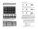
Switch S5-4: Enable Front Panel Swtiches
Use Switche S5-4 to enable or disable the front panel switches.
S5-4
Setting Description
On Enabled Front Panel Switches
enabled.
Off Disabled Front Panel Switches
disabled.
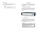
3.2CONFIGURE THE SOFTWARE SWITCHES
The Model 1092ARC features a menu-driven command system
that allows you to configure the local 1092ARC. The software control
port signals of the 1092ARC are carried to each card in the rack along
the internal power bus board. Access to all rack card control ports is
provided by a single PATTONModel 1001CC Control Card (see Model
Model 1001CC User Manual). After setting the control port address
(Section 3.1.3), use the following instructions to configure the unit:
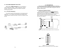
1) Connect the serial RS-232 port of a V100 or similar DTE with
terminal emulation to the EIA-561 control port on the Model
1001CC control card. To construct an RS-232 to EIA-561
patch cable, refer to the control port pinout diagram in
Appendix D. Refer to Appendix C to order a pre-made cable.
2) Power up the terminal and set its RS-232 port as follows:
9600 Baud
8 data bits, 1 stop bit, no parity
Local echo
CR-CR/LF on inbound data
ANSI, VT-100 emulation
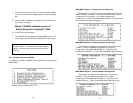
3. Press [CTRL+B] on the terminal followed by the two-digit
control port address.
12
The following table A-2 shows the bit setting to configure the
address.
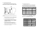
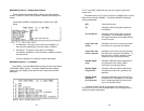
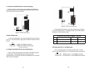
The configuration switches on S5 allow you to specify the data
rate, 2-wire/4-wire selection, and enable or disable loopback
diagnostics. Default settings of S5 are shown in the table below.
Switch S5-1: Data Rate
Use Switch S5-1 with Switches S1-1 and S1-2 to enable additional
data rates. The table in Section 3.1.2 shows all possible bit rate
settings for Switches S1-1, S1-2, and S5-1.
11
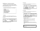
Position Function Factory Default
S5-1 Data Rate Off
S5-2 2-Wire/4-Wire Off 2-wire
S5-3 Enable LAL or RDL from DTE On Enable
S5-4 Front Panel Switch Control Off Enable
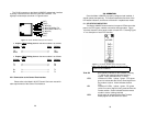
S5 SUMMARY TABLE
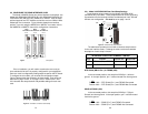
1- 2 - 3 - 4 - 5 - 6 - 7 - 8 - 9 - 10 - 11 - 12 - 13 - NMS - PS2 - PS1
TableA-1. Starting Address Setting
Upper (Lower) Nibble S2-7 S2-6 S2-5
(S2-4) (S2-3) (S2-2) (S2-1)
0 ON ON ON ON
1 ON ON ON OFF
2 ON ON OFF ON
3 ON ON OFF OFF
4 ON OFF ON ON
5 ON OFF ON OFF
6 ON OFF OFF ON
7 ON OFF OFF ON
8* OFF ON ON ON
9* OFF ON ON OFF
A* OFF ON OFF ON
B* OFF ON OFF OFF
C* OFF OFF ON ON
D* OFF OFF ON OFF
E* OFF OFF OFF ON
F* OFF OFF OFF OFF
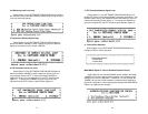
TableA-2. Bit Setting to Configure the Address
Address S2-7 S2-6 S2-5 S2-4 S2-3 S2-2 S2-1
(Dec.)
0x01 (1) ON ON ON ON ONONOFF
0x10 (16)
0x35 (53)
ON
ON
ON ONONON
ON
ON
ON
OFF
OFF
OFF
OFF
OFF
* 8 - F are only available for Lower Nibble.
3.1.4 Configuration Switch Set “S5”