


S1-5 and S1-6: Clock Source
Switches S1-5 and S1-6 are set in combination to determine the
transmit clock source for the Model 1140RC.
S1-5 S1-6 Setting
On On Internal transmit clock
Off On Receive recover clock
On Off External transmit clock
S1-7: Asynchronous/Synchronous Mode
The setting for switch S1-7 determines whether the Model 1140RC
is in asynchronous or synchronous operating mode.
S1-7 Setting
On Asynchronous
Off Synchronous
S1-8: Carrier Control Method
The setting for switch S1-8 determines whether the carrier is
“constantly on” or “controlled by RTS”. This setting allows for operation
in switched carrier, multipoint and/or hardware handshaking
applications.
S1-8 Setting
Off Constantly On
On Switched Carrier
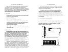
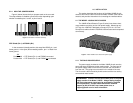
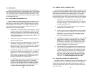
3.1.1 CONFIGURATION SWITCH SET “S1”
The DIP switches on S1 set data rate, clock source, async./sync.
mode and carrier control method. The default settings are summarized
in the table below. Following the table is a description of all possible S-
1 switch settings.
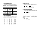
S1-1 through S1-4: Data Rate Setting
Switches S1-1 through S1-4 are set in combination to determine
the asynchronous and synchronous data rate for the Model 1140RC.
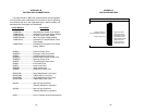
S1-1
S1-2 S1-3 S1-4 Setting
On On On On 1.2 Kbps
Off On On On 1.8 Kbps
On Off On On 2.4 Kbps
Off Off On On 3.6 Kbps
On On Off On 4.8 Kbps
Off On Off On 7.2 Kbps
On Off Off On 9.6 Kbps
Off Off Off On 14.4 Kbps
On On On Off 19.2 Kbps
Off On On Off 28.8 Kbps
On On Off Off 38.4 Kbps
Off On Off Off 57.6 Kbps
5 6
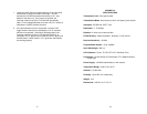
S1 SUMMARY TABLE
Position Function Factory Default
S1-1 Data Rate On
S1-2 Data Rate Off
S1-3 Data Rate Off
S1-4 Data Rate On
S1-5 Clock Source On
S1-6 Clock Source On
S1-7 Async./Sync. On Async.
S1-8 Carrier Control Off Constantly On
9,600 bps
Internal
}
}