


13
5.0 OPERATION
Once you have configured each Model 1140RC and connected the
cables, you are ready to operate the units. This section describes the
LED status monitors and power-up procedure.
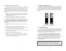
5.1 LED STATUS MONITORS
The Model 1140RC features ten front panel status LEDs that
indicate the condition of the modem and communication link:
• The green “PWR” LED glows when power is applied to the modem
card through its mid-plane chassis connection.
• The green “TD” and “RD” indicators blink to show positive state
data activity. The Red “TD” and “RD” indicators blink to show
negative state data activity. Solid red indicates an idle state.
• The green “RTS” and “CD” indicators glow solid to show the control
signal is on. The red “RTS” and “CD” indicators glow solid to show
the control signal is off. When the 1140RC is connected to a DTE,
RTS will glow green for an incoming signal on RS-232 pin 4. CD
will glow green for an incoming signal from the line, and an
outgoing signal on RS-232 pin 8.
• The “Test” LED glows when either the Local Analog Loopback
(LAL) or Remote Digital Loopback (RDL) V.54 test mode is
initiated. The “Error” LED blinks when an error is detected by the
V.52 diagnostics.
5.2 POWER-UP
There is no power switch on the Model 1140RC: Power is
automatically applied to the 1140RC when its card-edge connector
makes contact with the chassis’ mid-plane socket, or when the chassis’
power supply is turned on.
Note: The 1140RC is a “hot swappable”
card—it will not be damaged by plugging it in or removing it while the
rack is powered up.
When the local and remote units are
both
powered up, and are
passing data
normally
, the following LED conditions will exist:
• PWR = green
• TD & RD = flashing red and green
• RTS & CD = green
• Test = off
• Error = off
14
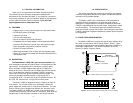
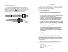
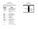
4.3.2 FIBER CONNECTIONS
The Model 1140RC is designed to work with the self-powered
Model 1140, or with another Model 1140RC. In either case, you will
need one unit at each end of a dual
fiber cable. This cable connects to
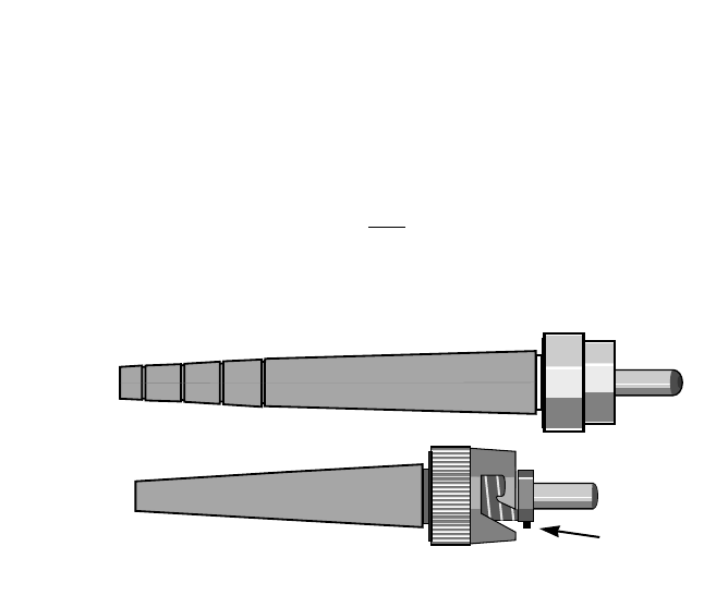
the Model 1140RC using either ST or SMA connectors. Figure 7
(below) shows a close-up of each of these connector types.
Figure 7. Close up of ST and SMA connections
ST
SMA
alignment pin
faces down