


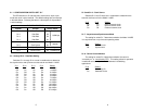
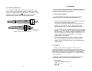
4.3 WIRING UP THE MODEL 1140RC
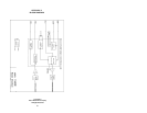
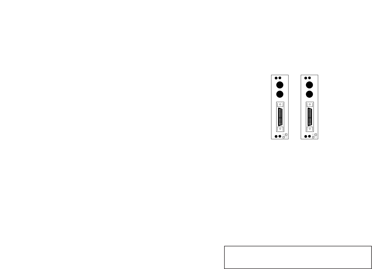
Both of the rear interface cards compatible with the Model 1140RC
have one RS-232 port and one dual-connector fiber port (see Figure 6.
below). Depending upon the card you have, the fiber port will be either
an ST or SMA connector. The RS-232 port is always a female HD-26
connector.
4.3.1 RS-232 CONNECTION
The RS-232 port on the rear card of the Model 1140RC is wired as
a DCE, and uses a female HD-26 connector. The HD-26 is an alternate
connector according to the EIA RS-232E specification, and the pin-out
is the same as a standard DB-25. Pin 26 is not used.
You will need an interface cable to connect the Model 1140RC to
your RS-232 device. Assuming your RS-232 device is a DTE (PC,
host, terminal, workstation, etc.), the cable should be wired
straight
through
. You may either provide your own cable, or you may purchase
an HD-26 to DB-25 cable from Patton Electronics Company. Please
call the Patton Sales Department at (301) 975-1000 for price and
delivery information.
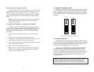
Switching the Power Supply On and Off
The power supply on/off switch is located on the front panel. When
plugged in and switched on, a red front panel LED will glow. Since the
Model 1000R16 is a “hot swappable” rack,
it is not necessary for any
cards to be installed before switching on the power supply
. The power
supply may be switched off at any time without harming the installed
cards.
NOTE: Please refer to the Model 1000RP Series User Manual
AC
and DC Rack Mount Power Supplie
s for fuse and power card
replacement information.
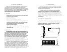
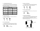
4.2 INSTALLING THE MODEL 1140RC INTO THE CHASSIS
The Model 1140RC is comprised of a front card and a rear card.
The two cards meet inside the rack chassis and plug into each other via
mating 50 pin card edge connectors. Use the following steps as a
guideline for installing each Model 1140RC into the Model 1000R16
rack chassis:
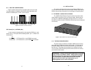
1. Slide the rear card into the back of the chassis along the metal
rails.
2. Secure the rear card using the metal screws provided.
3. Slide the front card into the front of the chassis. It should meet the
rear card when it’s almost all the way into the chassis.
4. Push the front card
gently
into the card-edge receptacle of the rear
card. It should “click” into place.
5. Secure the front card using the thumb screws.
NOTE: Since the Model 1000R16 chassis allows “hot swapping”
of cards, it is
not necessary to power down
the rack when you
install or remove a Model 1140RC.
1211
Dual SMA
Dual ST
Figure 6. Model 1140RC interface card options
A1
TX
RX
A1
TX
RX
HD-26 F
HD-26 F
Notice! Any terminal cable connected to the Model 1140RC
must be shielded cable, and the outer shield must be 360
degree bonded–at both ends–to a metal or metalized backshell.