


Connecting Power 18
CopperLink 1214 User Manual 2 • Installation
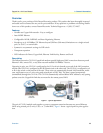
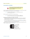
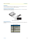
Connecting the POTS/ISDN Line (CL1214/S)
On the CL1214/S model, the RJ-45 port labeled is the POTS/ISDN interface. A telephone may be con-
nected to this port and carried over the CopperLink lin
e. The units do not need power for the POTS interface
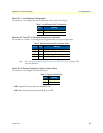
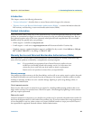
to work. The RJ-45 connector in the POTS/ISDN interface is wired as shown in figure 6.
1 (no connection)
2 (no connection)
3 (no connection)
4 (2-wire RING)
5 (2-wire TIP)
6 (no connection)
7 (no connection)
8 (no connection)
1
2
3
4
5
6
7
8
Figure 6. CL1214/S (RJ-45) POTS/ISDN interface.
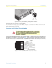
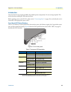
Connecting Power
CAUTION
The interconnecting cables shall be acceptable for external use
and shall be rated for the proper application with respect to volt-
age, current, anticipated temper
ature, flammability, and
mechanical serviceability.
The CL1214 does not have a power switch, so it powers up as soon as it is plugged in.
An external AC or DC power supply is available separatel
y. This connection is made via the barrel jack on the
rear panel of the CL1214. No configuration is necessary for the power supply (See Appendix B for domestic
and international power supply and cord options).
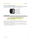
DC power (supplied via the power supply jack to the CL1214) must meet the following requirements; DC
po
wer supplied must be regulated 12VDC ±5%, 1.0A minimum. Center pin is +12V. The barrel type plug has
a 2.5/5.5/10mm I.D./O.D./Shaft Length dimensions.