


Introduction 23
CopperLink 1214 User Manual 4 • Operation
Introduction
Once the CL1214s are properly installed, they should operate transparently. No user settings required. This
section describes reading the LED status monitors.
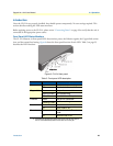
Before applying power to the
CL1214, please review “Connecting Power” on page 18 to verify that the unit is
connected to the appropriate power source.
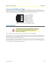
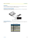
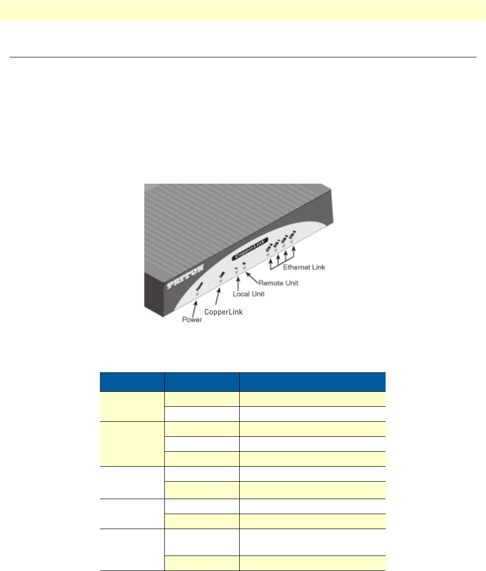
Front Panel LED Status Monitors
The CL1214 features six front panel LEDs that monitor po
wer, the Ethernet signals, the CopperLink connec-
tion, and the remote/local setting. figure 8 shows the front panel location of each LED. Tab le 5 on page 23
describes the LED functions.
Figure 8. CL1214 front pan
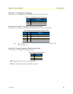
Table 5. Front panel LED description
LED Status Description
Power Green The device is powered on.
Off The device is powered off.
CopperLink Green The port is connected.
Blinking Green Data transceiving.
Off No valid link on this port.
Ethernet Green The port is connected.
a
a. Once the unit connects to a power source, the Link LED will blink as
the CL1214 automatically looks for the other unit in the pair.
Blinking Green
Data transceiving.
Local Green The device acts in Local mode.
Off Local mode is off.
Remote Green The device acts in Remote
mode.
Off Remote mode is off.
el