


29 30
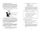
• “CTS” will glow green to indicate an On condition. When on,
the unit is ready to send data. If CTS remains off, check the
Forced RTS, Circuit Assurance and Anti-Stream settings.
• “CD” will glow green to indicate that a valid carrier is present.
If CD is not lit, there is no valid carrier signal detected.
• “DTR” will glow green to indicate that the DTR signal from the
terminal is active.
• “NS” will glow red to indicate No Signal. This means the
Model 2500RC Series receiver does not detect a signal from
the digital service provider (or, in the case of short-haul
operation, from the remote Model 2500RC Series). If NS is lit,
check for an unplugged cable, broken wire or an incorrect Line
Rate selection.
• “OS” glows red to indicate Out-of-Service. This means the
Model 2500RC Series has received an Out-of-Service signal
from the digital service provider and indicates a problem with
the service provider’s equipment. If this condition persists,
contact your service provider.
• “ER” glows red to indicate that an Error has been detected in
the received signal. ER will flash if the Model 2500RC Series
receives illegal bi-polar violations or framing errors. During the
511 or 511/E test, ER will flash to indicate that the Test Pattern
Detector has detected a bit error.
• “TM” glows red to indicate Test Mode. It will light if the unit is
placed into a test mode. The unit can be placed in test mode
by the local user, by the remote user or by the service
provider.
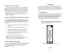
5.2 STATUS DISPLAYS
The Model 2500RC Series lets you use a VT-100 type RS-232
terminal to display the current configuration settings, as well as the
line/loop status.
Important: Please be sure you have read Section 3.2, and the Model
1000CC User Manual before attempting to implement the instructions
in the remainder of Section 5.2.
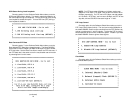
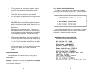
5.2.1 Displaying Configuration Settings
To display the current settings of the hardware and /or software
switches, go to the Main Menu and select item 2, “Read Configuration”.
This will take you to the Read Configuration Menu (below).
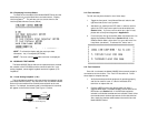
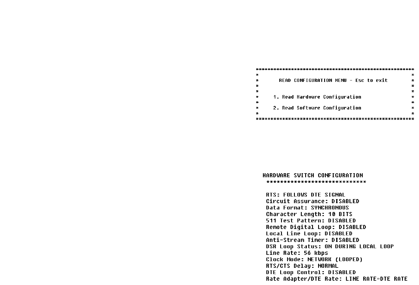
In the Read Configuration Menu, you may select item 1 to read the
hardware switch configuration or item 2 to read the software switch
configuration. A sample screens is shown below:
(continued)