


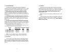
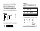
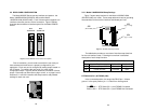
3.1.4 Setting Rotary Address Switches
If you plan to use the software control port to configure or dial the
Model 2500RC Series unit, you will need to configure each front card
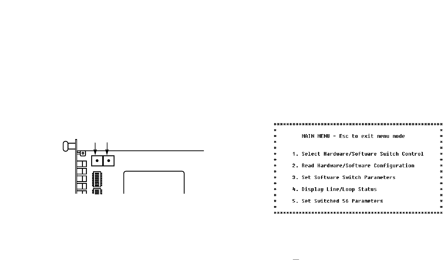
with a unique address. This is done by using a small screw driver to
set the two rotary switches, as shown in Figure 4, below. The switches
are set individually for a number from 0 - 9, forming a two digit address
(00 - 98). Software commands set to a particular address will be
recognized by the card with that address, and ignored by other cards.
Note: Address “99” is universal. All units respond to address “99”
no matter how the rotary switches are set.
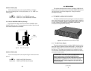
3.2 FRONT CARD CONFIGURATION - SOFTWARE SWITCHES
The Model 2500RC Series has an internal control port that allows
software configuration. Control port signals are carried to each card in
the rack along the power bus board inside the rack chassis. Access to
all rack card control ports is provided by a single Patton Model 1000CC
control card. For instructions on installation and use of the Model
1000CC, please refer to the Model 1000CC User Manual.
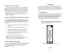
3.2.1 Accessing the Software Control Port
Once you have set each Model 2500RC’s address (see Section
3.1.4), plugged each front card into the rack chassis (see Section 4.0),
and properly installed the Model 1000CC control card (see Model
1000CC User Manual), you are ready to access the Model 2500RC
Series Main Menu. Follow these steps:
1. Connect the serial RS-232C port of a VT100 terminal (or
similar RS-232 DTE with terminal emulation) to the EIA-561
control port on the Model 1000CC control card.
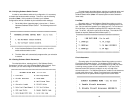
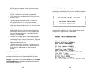
2. Power up the terminal and set its RS-232C port as follows:
9600 baud
8 data bits, 1 stop bit, no parity
local echo
CR = CR/LF on inbound data
ANSI, VT-100 emulation
3. Press [CTRL+B] on the terminal, then enter the address of the
card you wish to configure (see Section 3.1.4), and press
[RETURN]. (Note: Do
not
use the universal address [99].
Configure only
one
card at a time.) The Model 2500RC Series
Main Menu should then display on the terminal screen (see
below).
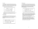
3.2.2 Using the Software Menu System
The Model 2500RC Series Menu System operates as follows:
1 All selections must be followed by [RETURN].
2 To make a selection from any menu, enter the option number
at the prompt and press [RETURN].
3. To exit any menu without making a selection, press [ESC]
followed by [RETURN]. (Note: You can also exit by just
pressing [RETURN]. However, doing this in the Store Phone
Number Menu will clear the buffer of the currently stored
number.)
13 14
Figure 4. Setting the rotary address switches
ON
12345678
678
LSD
MSD
Rotary Address
Switches