


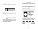
Switch SW3 and SW4: Clock Mode
SW3 is used to along with SW4 to determine the clock mode. For
example the Model 2702 can be set to external clock mode by setting
both SW3 and SW4 to the on position. Please refer to the Clock Mode
chart below for the desired settings.
CLOCK MODES
Network Clock Transmitter timing is derived from the received line
signal.
Internal Clock Transmitter clock is derived from an internal clock
source
External Clock Transmitter timing is derived from the local DTE
device. A 2.048 MHz timing signal must be present a
at the external clock pin U and pin W on the M/34
connector.
Note: When using the 2702 as a high-speed short range modem, one
unit of the link must be configured in either internal or external clock,
and the other end must be configured for network clock mode, or both
units could be either Internal or External Clock. But both units cannot
be network clock mode in SRM applications
9
CLOCK MODE SETTINGS
SW3 SW4 Clock Mode
Off Off Network (Default)
Off On Internal
On On External
On Off Network
4.0 INSTALLATION
The Model 2702 is equipped with DTE, network, and power interfaces.
This section briefly describes connection to each.
4.1 DTE INTERFACE CONNECTION
The DTE/DCE interface is a V.35 DCE presented as an M/34 male
connector. This interface is designed to plug directly into a DTE inter-
face (See Appendix D for V.35 interface pin assignments).
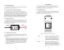
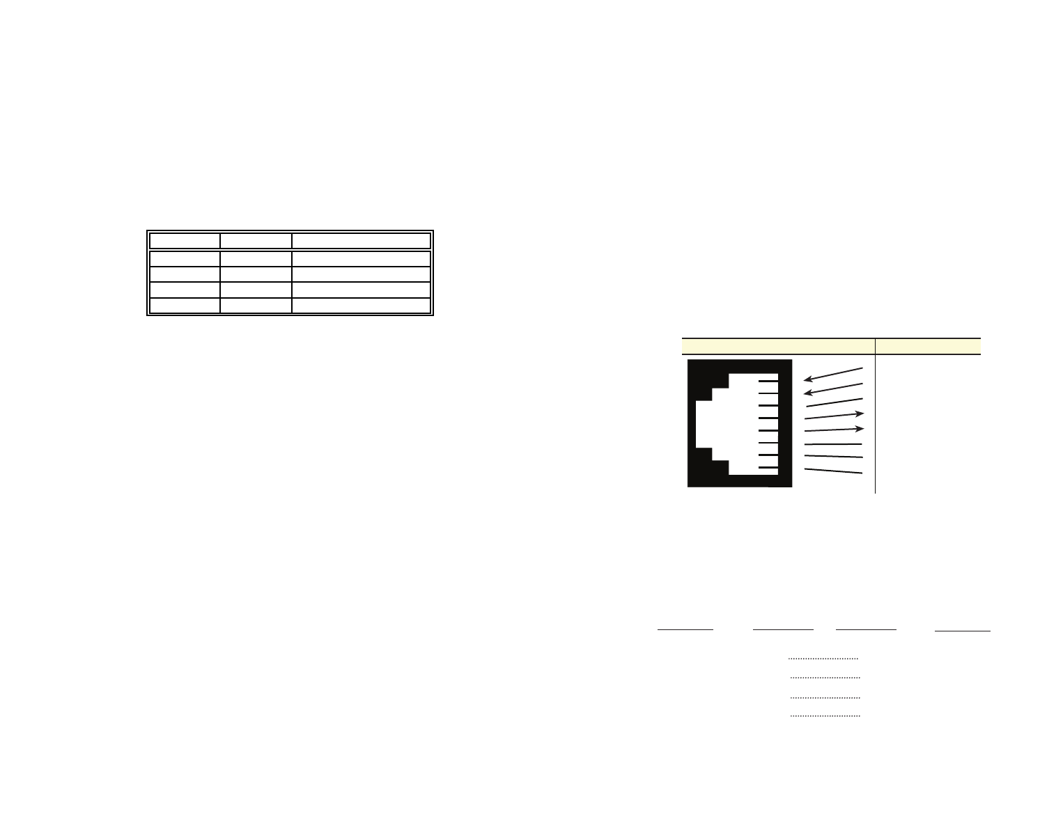
4.2 NETWORK INTERFACE CONNECTION
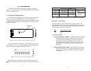
The Network Line Interface is an eight position keyed modular jack
configured as a RJ-48C. This interface will need to be configured to
match the line parameters (i.e. framing, line coding, etc.) supplied by
the central office.
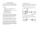
NOTE: If the Model 2702 is being used for private short range
modem applications, the twisted pair cable connected to its port
will need to be a cross-over cable, and should be configured as
shown below. See Appendix D for Interface pin assignments.
10
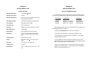
Figure 3. Model 2702 twisted pair lineinterface.
SIGNAL PIN NO. PIN NO. SIGNAL
RX Data (Ring)
1 4 TX Data (Tip)
RX Data (Tip)
2 5 TX Data (Ring)
TX Data (Ring) 4 1 RX Data (Ring)
TX Data (Tip) 5 2 RX Data (Tip)
1
2
3
4
5
6
7
8
1
2
3
4
5
6
7
8
(RX) Receive (Ring)
(RX) Receive (Tip)
Shield
(TX) Transmit (Ring)
(TX) Transmit (Tip)
Shield
No connection
No connection
Signal NameRJ-48C Jack