13
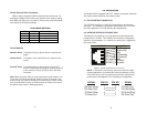
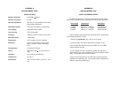
LOTC The Loss of Transmit Clock LED lights
when
the unit detects that there is no transmit
clock.
ALM The alarm LED indicates the loss of carrier,
i.e., no activity on the network.
ERR The error LED is not used in Model 2702.
TST The test indicator LED blinks with a specific
pattern depending on the type of test mode.
When the unit is in local analog loop, the
LED will blink on briefly. When the unit is in
remote loop, the TST LED will blink off
briefly. The test mode is V.54 Loopback &
Local loopback.
PWR The power indicator LED will remain lit while
the unit is powered. It turns off when the
unit is not powered.
5.2 LOOP (V.54 & TELCO) DIAGNOSTICS
The Model 2702 offers two V.54 loop diagnostics and is compati-
ble with two Telco loop diagnostics. Use these diagnostics to test the
NTU and any communication links. These tests can be activated via
signals on the DTE interface.
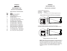
5.2.1 Operating Local Loopback (LL)
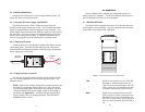
The Local Loopback (LL) test checks the operation of the local
Model 2702, and is performed separately on each unit. Any data sent
to the local Model 2702 in this mode will be echoed (returned) back to
the user device. To perform a LL test, follow the steps below.
1. Activate the “LL” signal on the DTE pin L. If you are not sure
which lead is the “LL” signal, please refer to Appendix D.
2. Verify that the data terminal equipment is operating properly
and can be used for a test.
3. Perform a V.52 BER (bit error rate) test. If the BER test equip-
ment indicates no faults, but the data terminal indicates a
fault, follow the manufacturer’s checkout procedures for the
data terminal. Also, check the interface cable between the
terminal and the Model 2702.
14
5.2.2 Operating Remote Digital Loopback (RL)
The Remote Digital Loopback (RL) test checks the performance of
both the local and remote Model 2702, as well as the communication
link between them. To perform a RDL test, follow the steps below.
1. Activate the “RL” signal on the DTE pin N. If you are not sure
which lead is the “RL” signal, please refer to Appendix D.
2. Perform a bit error rate test (BERT) or using a separate BER
Tester. If the BER test indicates a fault, and the Local Line
Loopback test was successful for both NetLink™s, you may
have a problem with the twisted pair line connection.


