4.3 POWER CONNECTION
The Model 2702 offers three ways to supply external power: AC
power, DC power and interface power.
4.3.1 Using the AC Power Supply (100-240VAC)
The Model 2702 uses a 5VDC, 400mA universal input 100-
240VAC, power supply (center pin is +5V). The universal input power
supply is equipped with a male IEC-320 power entry connector. This
power supply connects to the Model 2702 by means of a barrel jack on
the rear panel. There are a variety of international power cords avail-
able for the universal power supply. The Model 2702 powers up as
soon as it is plugged into an AC outlet–there is no power switch.
4.3.2 Supplying DC Power
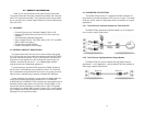
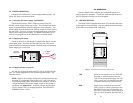
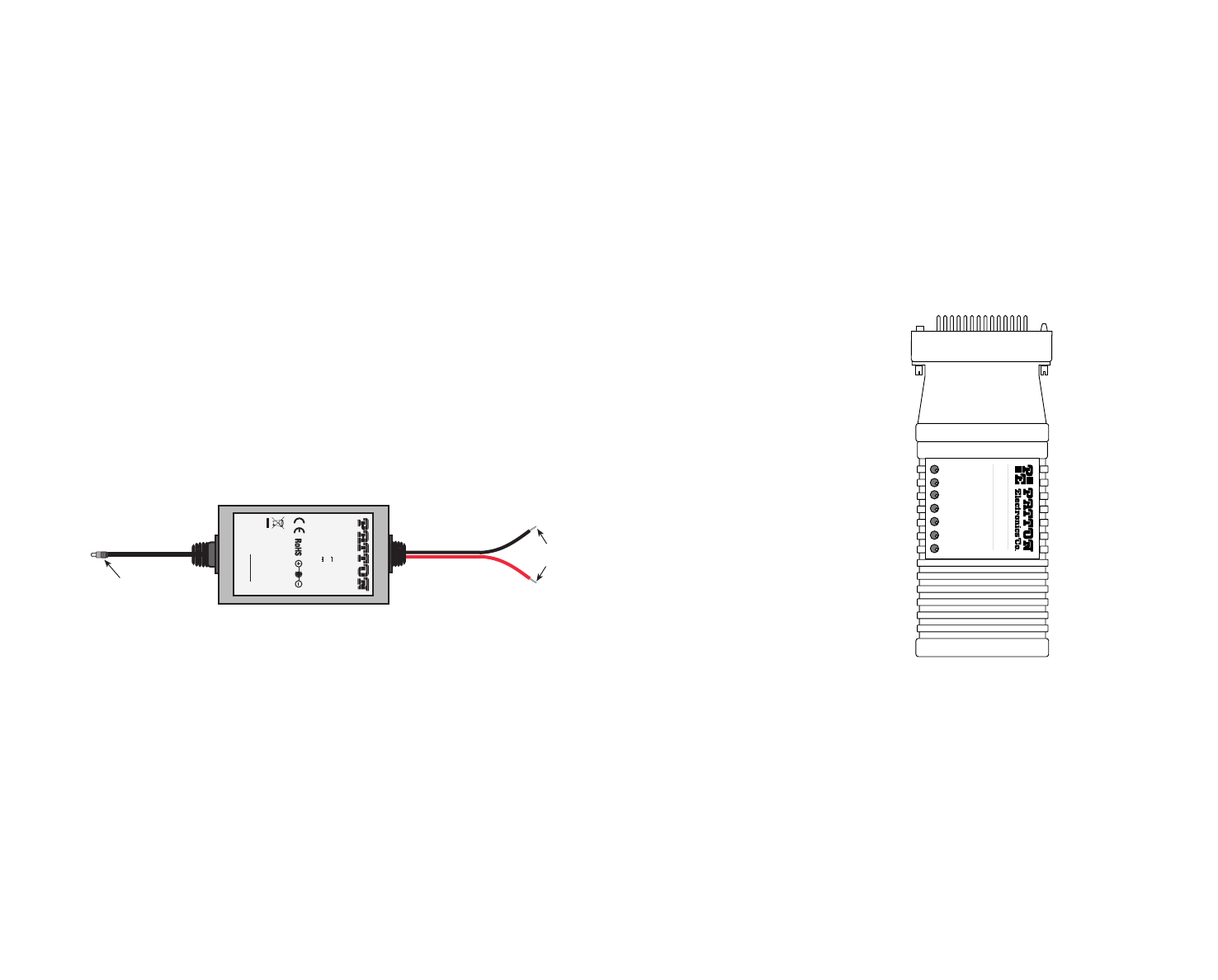
The 36-60 VDC DC to DC adapter is supplied with the DC version
of the Model 2702. The black and red leads plug into a DC source
(nominal 48VDC) and the barrel power connector plugs into the barrel
power supply jack on the 2702.
4.3.3 Supplying Power via pin KK
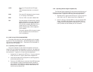
You may also supply DC power directly to pin KK of the V.35 inter-
face. DC Power supplied to pin KK must be regulated 5VDC ± 5%,
300mA minimum.
NOTE: Model 2702 is factory configured to accept power from the
enclosed DC wall adapter (See Sections 4.3.1 and 4.3.2 above).
If you wish to supply power via pin KK on the interface, you must
change the setting of the
power supply jumper
on the printed cir-
cuit board See Appendix E. All power sources must be SELV
(Circuit, Safety Extra Low Voltage) specified. (See CENELEC
EN60950, Section 1.2.8.5)
11
5.0 OPERATION
Once the Model 2702 is installed and configured properly it is
ready to place into operation. This section describes the function of
the LED indicators, and the use of the loopback.
5.1 LED DESCRIPTIONS
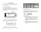
The Model 2702 is equipped with seven LED indicators that moni-
tor the status of communication. Figure 4 (below) shows the location
of the LEDs on the Model 2702 front panel.
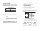
TXD When the unit sends a one, the TXD LED
is turned on. When it sends a zero, the
TXD LED is turned off. Moreover, the TXD
LED is active only in active DS0 channels.
In inactive channels, the TXD LED is off.
RXD When the unit receives a one, the RXD
LED is turned on. When it receives a zero,
the RXD LED is turned off. Moreover, the
RXD LED is active only in active DS0 chan-
nels. In inactive channels, the RXD LED is
off.
12
RXD
LOS
ALM
ERR
T/L
PWR
TXD
Model 2702
G.703 Interface Converter
Figure 4. Top of Model 2702, Showing LED Indicators
To Power
Supply Jack
To -48VDC
Source
-Vin
+Vin
SWITCHING POWER SUPPLY
MODEL : SYD1106-0505
INPUT : 36-60V 0.2A MAX
OUTPUT : +5V 1.0A
OUTPUT POWER : 5W MAX
S/N: G01234567890
MADE IN CHINA BY SUNNY
Black lead (-V)
Red lead (+V)
Barrel power connector


