


137001UA
2-4
Setup & Installation
3012-14-18/V24
INSTALLATION AND OPERATIONS MANUALPATTON
ELECTRONICS CO.
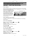
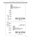
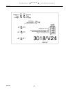
Switching Mode Selection (Switch Pos 5)
3014/V24 (CTS MSD-4C) & 3018/
V24 (CTS MSD-8C) Only
To select Priority Mode, set switch position 5 to
ONON
ONON
ON. To select Scanning Mode, set
switch position 5 to
OFFOFF
OFFOFF
OFF. The Modem connected to the master port of the MSD
must toggle CTS in response to RTS for the MSD to operate correctly. In addition,
the terminals connected to the ports must toggle RTS to gain control of the unit. If
the terminal will not toggle RTS, it will not work with an MSD.
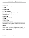
CTS Delay on the 3012/V24 (CTS MDS-2C) (Switch Pos 5)
If a 25 mS CTS delay is desired, set switch position 5 to
ONON
ONON
ON. If no delay is required
set switch position 5 to
OFFOFF
OFFOFF
OFF.
CTS Delay on the 3014/V24 (CTS MSD-4C) & 3018/V24 (CTS MSD-8C) (JP6)
If a 25 mS CTS delay is desired, install the CTS Delay Jumper.
Unregulated Power to Pins 9 & 10
Jumpers JP4 and JP5 must be installed to provide unregulated power on pins 9 &
10 on the port DB-25 connectors.
Factory Test Jumpers (JP1,JP2,JP3)
The three test jumpers JP1, 2 and 3, must be installed for the unit to properly
function. These jumpers are used in the manufacture and test of the product prior
to shipment.